
Solar panel circuit

The schematic outlines the necessary components and their interconnections to achieve the desired functionality of illuminating an LED. The design typically includes a power source, such as a battery or DC power supply, which provides the necessary voltage and current. The LED requires a current-limiting resistor to prevent excessive current from damaging the diode.
In the schematic, the power source is connected to the anode of the LED through the resistor, while the cathode of the LED is connected to ground. This arrangement ensures that when the circuit is powered, current flows through the resistor and the LED, causing the LED to emit light.
Additional components may include a switch to control the circuit, allowing the user to turn the LED on and off. The PCB layout must consider the physical placement of components to minimize interference and optimize space. Proper routing of traces is essential to maintain signal integrity and prevent issues such as crosstalk or voltage drops.
The PCB design process also involves selecting appropriate materials, such as FR-4 for the substrate, and determining the thickness of the copper traces to ensure they can handle the required current without overheating. The final design can then be used to create a copper circuit board, which will be populated with the components and soldered to form a functional electronic device.A printed circuit board (PCB) and showed us a schematic of components that needed to be put onto the board in such a way so that an LED on the board would light up. The point of the PCB is so that you can plan for when you have a real copper circuit board that you are actually going to solder onto.
🔗 External reference
Related Circuits

The IR Jammer is a fun project that provides a bit of safe, non-destructive fun. The Infrared Remote Control Jammer allows you to render all IR remote controls inoperative! The microcontroller in this design allows for all 6 of...

The East Shi IDS-2000F STB switching power supply circuit primarily consists of an AC input circuit, a switching oscillation circuit, an output circuit, and a secondary steady voltage control circuit. The AC input circuit includes a switch (S), fuse...
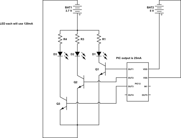
This is a conceptual schema utilizing a PIC12 microcontroller to control the blinking of three LEDs, each exhibiting different blinking patterns. There are several questions that need to be addressed. The circuit design involves a PIC12 microcontroller, which is a...

The AD650 is a voltage-to-frequency (V/F) and frequency-to-voltage (F/V) converter that offers high-frequency operation and low nonlinearity, features that were previously unavailable in a monolithic form. Its inherent monotonicity in the V/F transfer function makes the AD650 suitable for...

The 555 Timer has extensive applications in electronics. This document describes the use of the 555 Timer in a monostable multivibrator configuration to trigger a transistor driver that energizes a relay, which in turn operates a 230V AC lamp...
This circuit utilizes a photoelectric coupler to achieve 100GΩ isolation between a TTL (Transistor-Transistor Logic) circuit and a relay circuit. This configuration effectively prevents relay noise and peak voltage from affecting the TTL circuit. When the TTL input signal...