
Solar Panel Current Meter

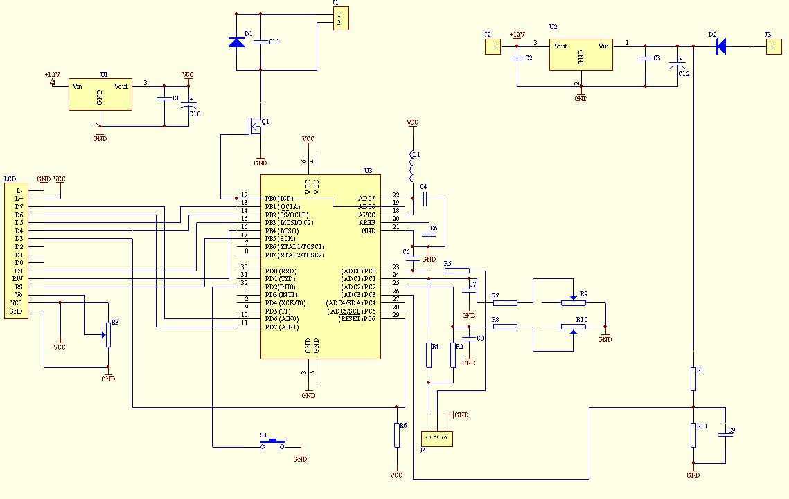
The circuit described is a DC current measurement system designed specifically for low power loss, making it suitable for applications such as solar panel monitoring. The primary operational range of the circuit is from 0 to 10 Amperes, allowing it to accurately measure the output current from solar panels, which typically operate within this range under normal conditions.
The design incorporates a shunt resistor, which is a crucial component for current measurement. The shunt resistor is placed in series with the load, and the voltage drop across it is proportional to the current flowing through it, as described by Ohm's Law (V = I × R). A differential amplifier or an operational amplifier (op-amp) is often used to amplify this voltage drop for easier reading and processing. The low power loss characteristic is achieved by selecting a shunt resistor with a low resistance value, minimizing the voltage drop and power dissipation.
Additionally, the circuit can be configured to measure current on either the positive or negative side of the DC circuit, providing versatility in installation and application. This feature is particularly beneficial in solar applications where the orientation of the panel and the connection points may vary.
For visualization and interfacing, the output from the amplifier can be connected to an analog-to-digital converter (ADC) for digital readout or displayed directly on a voltmeter or LCD screen for real-time monitoring. Calibration of the circuit may be necessary to ensure accurate readings, taking into account the resistor's tolerance and any potential temperature coefficients.
Overall, this circuit serves as a reliable and efficient tool for monitoring DC currents, particularly in renewable energy applications, ensuring that users can effectively track performance and system health.This circuit is used to measure the current from a solar panel. It has very low power loss for currents in the 0-10A range. It also works as a general purpose DC current meter. The circuit can be used on either the positive or negative side of a DC circuit. 🔗 External reference
Related Circuits
This solar tracker circuit is an open-source design that allows for modifications according to individual preferences. A video is available that provides additional useful information regarding the features included in the solar tracker, as well as those that may...
The input signal is applied to a gate G and then to a counter for a precise period of time. After this period, the input signal is stopped for a while, and then the cycle is repeated. During the...
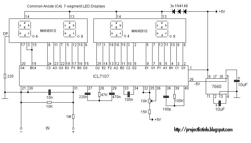
This digital voltmeter is suitable for measuring the output voltage of a DC power supply. It features a 3.5-digit LED display with a negative voltage indicator, capable of measuring DC voltages from 0 to 199.9V with a resolution of...
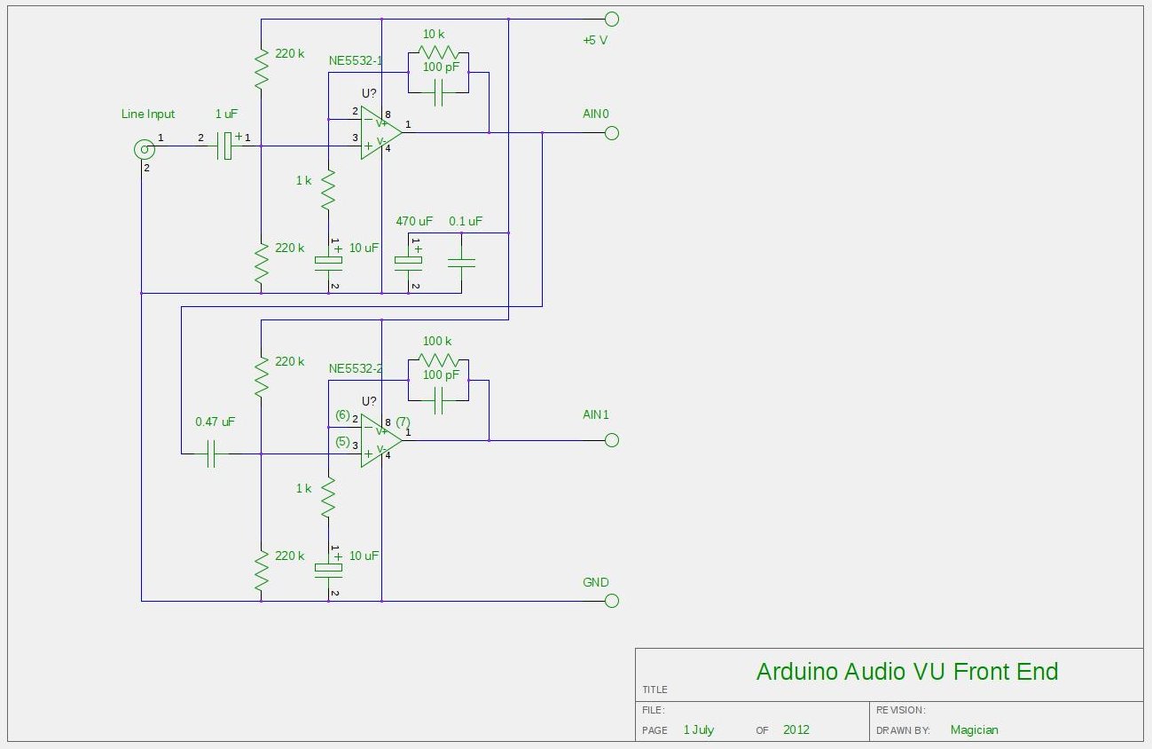
After experimenting with a stereo version of the VU meter described in a previous blog post, a studio-grade VU meter is now being presented. This meter features 24 steps, spaced equally every 3 dB, and covers a wide dynamic...
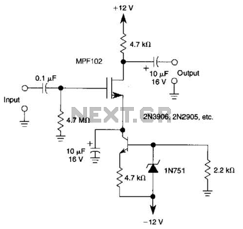
A current source (MPF102) in the source lead of the bipolar transistor 2N3906 allows for precise control of drain current. The circuit incorporates an MPF102 JFET configured as a current source, which is connected to the source terminal of a...
This multimeter was designed to measure output voltage and current in a PSU, where the current sense shunt resistor is connected in series with load at the negative voltage rail. It needs only one supply voltage that can be...