
Solar Panel to Battery Switch Circuit

The described circuit operates as an efficient solar battery charger, utilizing a relay to manage the connection between the solar panel and the battery. The fundamental components include a solar panel, a relay, a light-dependent resistor (LDR), a transistor (T1), and resistors (R2 and P1).
During daylight, the solar panel generates sufficient voltage to engage the relay, which closes the circuit and allows current to flow from the solar panel to the battery, charging it. The LDR plays a critical role in detecting ambient light levels. When the light intensity is above a certain threshold, it allows T1 to conduct, thus energizing the relay coil and maintaining the relay in the 'ON' state. This design effectively prevents reverse current flow from the battery back into the solar panel during the night or in low-light conditions.
Resistor R2 is strategically placed to ensure that once the battery is charged, it cannot activate the relay when the light intensity falls below the set threshold. This feature is essential for preventing battery discharge through the solar panel during times when there is insufficient solar energy.
The adjustment of potentiometer P1 allows for fine-tuning of the light sensitivity of the circuit, enabling the user to set the precise brightness level at which the relay will disengage. This flexibility ensures optimal performance under varying environmental conditions.
The choice of a miniature relay with high coil resistance is vital for minimizing power consumption, as the relay itself is the primary load in this circuit. The relay must be capable of handling a load of up to 10 Amps, ensuring it can accommodate various battery charging scenarios without overheating or failing.
Overall, this solar panel power switch circuit presents a robust solution for efficient solar energy utilization, protecting the battery from unnecessary discharge while ensuring reliable charging during daylight hours.When loading a battery during the day from a solar panel it can be partially discharging through the panel after nightfall. This solar panel power switch circuit replaces the diode and connects the panel to battery through a relay contact.
When the voltage is high enough to engage the relay and the LDR receives enough light in order to open T1, the relay will switch and the battery will charge. The relay remains ON even when the solar panel voltage starts to decrease. A battery connected and charged can not action the relay when the light intensity decreases because R2 will block T1. The brightness at which this occurs is set by P1. Because the power consumption is determined primarily by the relay, it is important that the relay should be a miniature one, with high coil resistance but also be capable to switch up to 10 Amps.
🔗 External reference
Related Circuits
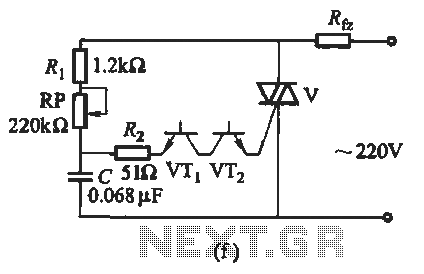
The introduction for a unidirectional thyristor trigger circuit is also applicable to the TRIAC. Various configurations are presented in Figure 16-28. Figures 16-28 (a) and (b) illustrate a direct trigger circuit; Figure 16-28 (c) depicts a dual diode trigger...
One 1381 part (CMOS voltage-controlled trigger available at different limits) should be selected to match the voltage across the motor (2V in this case). The other terminal of the motor is connected to a 3300µF capacitor, which is in...
This simple alarm timer circuit is constructed using a 4060 IC, which features an integrated oscillator known for its good stability and relatively wide frequency range. The 4060 integrated circuit (IC) serves as the core component of this alarm timer...
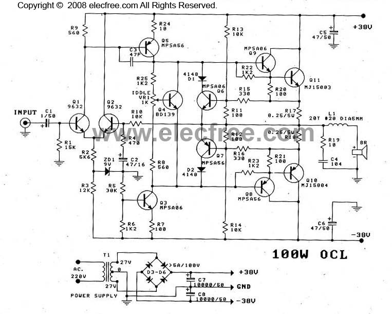
This OCL 100W power amplifier offers excellent sound quality. The circuit features direct coupling throughout to minimize low-frequency cut-off issues, enhancing super bass performance. The input signal for the tone controls enters via capacitor C1 to the base pin...
Switching to alternative power sources can lead to savings on electricity bills. The photovoltaic module or solar panel discussed here has a power output of 5 watts. Under full sunlight conditions, the solar panel generates 16.5V and can provide...
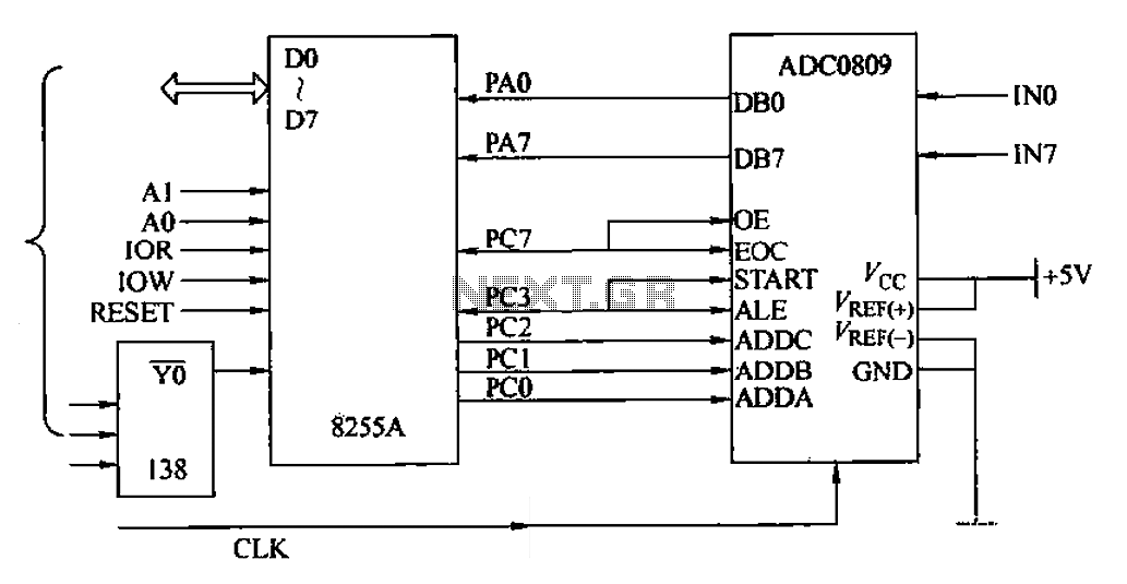
The ADC0809 is an 8-channel analog switch integrated with an 8-bit successive approximation analog-to-digital (A/D) converter. It supports the selection of eight input channels through address latch and encoder channel selection signals ADDA, ADDB, and ADDC. The address latch...