
Solar Powered Robot

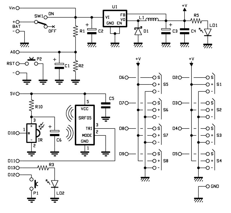
This robot can be designed using basic electronic components to create a simple activation mechanism based on light detection. The core of the circuit can include a light-dependent resistor (LDR) as the primary component for detecting light from the desk lamp. The LDR will change its resistance based on the intensity of the light it receives.
In the schematic, the LDR should be connected in a voltage divider configuration with a fixed resistor. The output of this voltage divider can be fed into a transistor, which acts as a switch. When the light from the desk lamp shines on the LDR, the resistance decreases, causing the voltage at the transistor's base to rise. This will turn the transistor on, allowing current to flow from the power supply to the robot's motor or actuator, thereby activating the robot.
A microcontroller can also be integrated into the design to allow for more advanced control features, such as adjusting the sensitivity of the light detection or incorporating additional functionalities like movement patterns. However, for a basic version, the combination of an LDR, a resistor, and a transistor will suffice to create an effective light-activated robot.
Power supply considerations should include a suitable battery or power adapter that matches the voltage requirements of the motor and other components. Additionally, it is advisable to include a diode across the motor terminals to prevent back EMF from damaging the circuit when the motor is turned off.
Overall, this robot provides a straightforward introduction to basic robotics and electronic principles, making it an ideal project for beginners.Make a very cheap, relatively easy to construct robot which will wake up any time you shine a desk lamp on it. There are no sensors on it, although I.. 🔗 External reference
Related Circuits
This device is designed to be a simple, inexpensive comparator intended for use in a solar cell power supply setup where a quick "too low" or "just right" voltage indicator is needed. The circuit consists of one 5V regulator,...
The objective of this post is to consolidate various robot designs and transform them into a new device featuring updated hardware and standardized software, specifically using Arduino, to enhance usability. These robots share three common elements: a mechanical structure,...
The typical home solar power system primarily comprises a roof-mounted solar panel, a charge controller, and a storage battery bank, along with direct or electric connections. A home solar power system is designed to harness solar energy for residential use,...
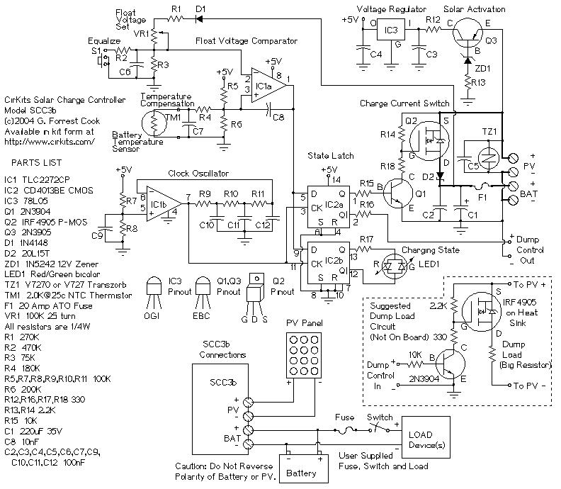
SCC3 12 Volt 20 Amp Solar Charge Controller. A kit with the circuit board and parts for this circuit is available from CirKits. SCC3 - 12 Volt 20 Amp Solar Charge Controller (C) G. Forrest Cook June. The SCC3 Solar...
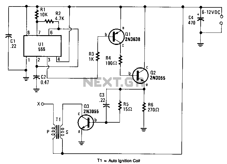
An output voltage sufficient to bridge a one-inch gap can be generated from a 12-V power source. A 555 timer integrated circuit (IC) is configured as an astable multivibrator, producing a narrow negative pulse at pin 3. This pulse...
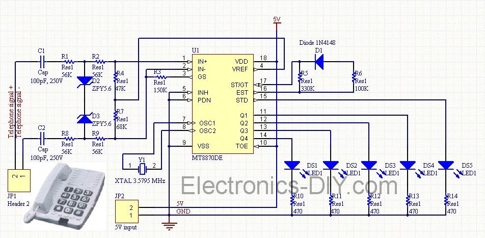
Cellphone Operated Land Rover (Mobile Phone Operated Robot). In this project, the robot is controlled by a mobile phone that makes a call to the mobile phone attached to the robot. The cellphone operated Land Rover project involves the design...