
Solar Tracking Circuit
The solar tracking circuit utilizes a combination of photovoltaic (PV) cells, sensors, and a microcontroller to adjust the orientation of solar panels in real-time, ensuring they are always positioned to capture the maximum amount of sunlight. The key components of the circuit include light-dependent resistors (LDRs) that detect the intensity of sunlight on different sides of the panel. These sensors provide feedback to the microcontroller, which processes the data and actuates motors to tilt or rotate the solar panels accordingly.
The circuit typically features a dual-axis tracking mechanism, allowing the solar panels to move both horizontally and vertically. This is achieved through the use of servo motors or stepper motors, which are controlled by the microcontroller based on the input from the LDRs. The design also incorporates a power management system that regulates the output voltage and current generated by the solar panels, ensuring it is suitable for charging batteries or powering electronic devices.
In addition to the core components, the circuit may include protection features such as diodes to prevent reverse current flow, capacitors for smoothing the output, and voltage regulators to maintain stable output levels. The overall efficiency of the solar tracking circuit is significantly enhanced compared to fixed solar panels, as it maximizes energy capture throughout the day, adapting to the sun's trajectory.
This solar tracking circuit represents an effective solution for renewable energy generation, contributing to sustainable practices by optimizing the use of solar energy.Here is solar tracking circuit. This circuit is a power generating method from sunlight. This circuit need only maximum sunlight to generate power. This project. 🔗 External reference
Related Circuits
This is a battery charger circuit that has the advantage of automatically disconnecting the battery when charging is complete. The voltage sensor used in this circuit is the LM301 IC, which serves to disconnect the battery when the charging...
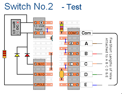
The prototype of Keypad Switch No. 2 was constructed using only the stripboard layout as a reference. If the layout has been accurately reproduced, a functional circuit will result. Once the layout is confirmed to be correct and a...
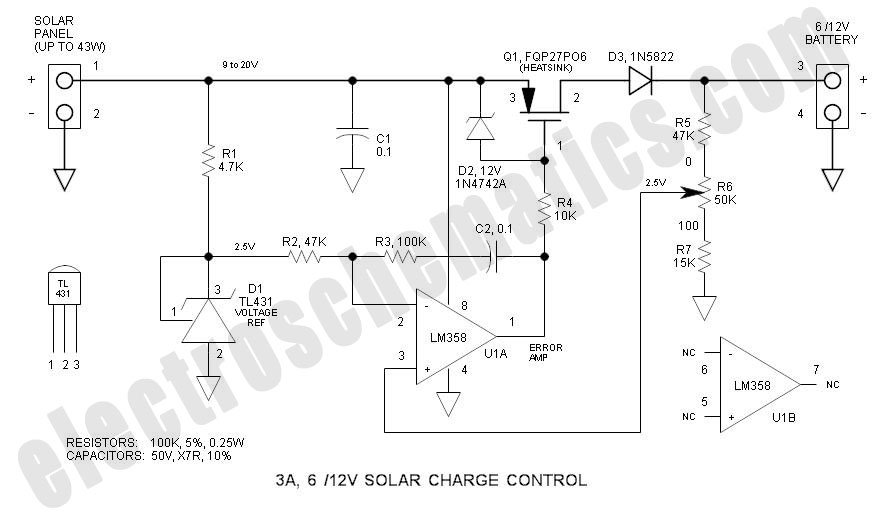
This solar charge controller integrates multiple features into a single design, including a 3A current rating, low dropout voltage (LDO), and a range of voltage adjustment capabilities. The solar charge controller is a critical component in solar energy systems, tasked...
This circuit is a simple IR detector for testing IR remote controllers. The circuit is based on one phototransistor which receives the IR beam. The NPN transistor works as an amplifier which feeds current to the LED. When this...
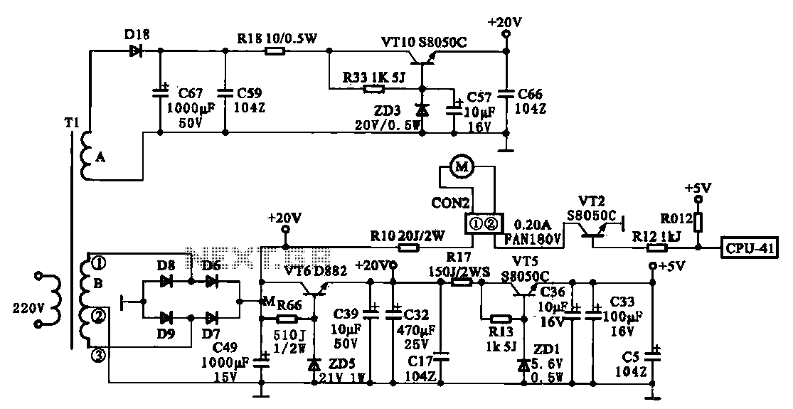
The JYC-22F type cooker low voltage power supply circuit is depicted. An AC 220 V power supply voltage is applied to a low-voltage transformer. The transformer has a primary winding (Tl) and two secondary windings (A and B), with...
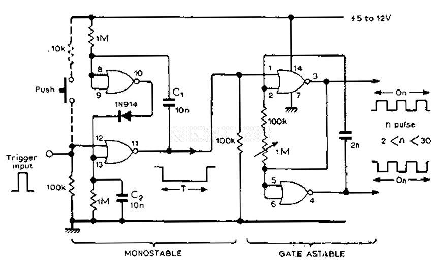
Each trigger input can produce a fixed number of pulses, with the range being from 2 to 30. The specific number is determined by the frequency-controlled settings of 1 megohm. A monostable gated unsteady power supply circuit can be...
Warning: include(partials/cookie-banner.php): Failed to open stream: Permission denied in /var/www/html/nextgr/view-circuit.php on line 713
Warning: include(): Failed opening 'partials/cookie-banner.php' for inclusion (include_path='.:/usr/share/php') in /var/www/html/nextgr/view-circuit.php on line 713