
Joyoung JYC-22F-type low-voltage power supply circuit

The JYC-22F low voltage power supply circuit is designed to efficiently convert and regulate voltage for use in various applications, particularly in cooking appliances. The circuit begins with an AC input of 220 V, which is transformed down to a lower voltage through the primary winding of the transformer. The dual secondary windings provide flexibility for voltage regulation and distribution.
The bridge rectifier is crucial for converting the AC voltage from the transformer into a usable DC voltage. This conversion process ensures that the output voltage is smooth and stable, suitable for powering sensitive electronic components. The output at point M, which is 20 V DC, is then split into two paths for different functionalities: one feeds the fan directly, while the other is routed to the microprocessor and voltage regulation components.
The fan operation can be automated or manually controlled. When the microprocessor sends a high signal to the base of transistor VT2, it activates the fan, allowing it to operate as needed based on system requirements. This integration of a microprocessor adds an intelligent control mechanism to the circuit, enhancing its functionality.
The voltage regulation section of the circuit is designed to maintain a consistent output voltage. Transistor VT6, in conjunction with Zener diode ZD5, ensures that the voltage remains at 20 V, which is essential for stable operation. The subsequent regulation through ZD1 and VT5 provides a lower output of +5 V DC, which can be used to power lower voltage components within the system.
Overall, the JYC-22F type cooker low voltage power supply circuit exemplifies a well-structured design that combines power conversion, regulation, and control, making it suitable for various electronic cooking applications. The careful consideration of component selection and circuit topology ensures reliable operation and efficient performance in real-world conditions.JYC-22F type cooker low voltage power supply circuit is shown. AC 220 V power supply voltage is applied to low-voltage transformer Tl primary, it has two secondary windings A and B, B middle winding has a tap, so it has the O, , three terminals. O and two terminals through a bridge rectifier circuit AC into DC output voltage is 20 V DC. 2 () V DC voltage at the point M is divided into two, all the way through the connector CON2 sent to the fans of O feet, CON2's feet as long as the ground, fans will be able to rotate.
feet off the ground, or is controlled by a microprocessor. The microprocessor has a high level is applied to the crystal tube VI2 the base of transistor VT2 is turned on, current flows through the electric fans, electric fans can be rotated. Another way is separated from the M point regulator circuit, the base of the transistor VT6 has zener diode ZD5, After a regulator transistor VT6 + emitter output voltage of 20V.
+ 20V voltage regulator circuit consists of a transistor and then through the Zener diode ZD1 VT5 and composed, you can output +5 V DC voltage.
Related Circuits
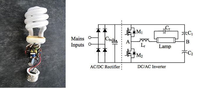
A circuit diagram for a 40W, 230V transistor-based electronic ballast is required. What steps are involved in designing an electronic ballast? An electronic ballast is a device used to regulate the current to fluorescent lamps and provide sufficient voltage to...
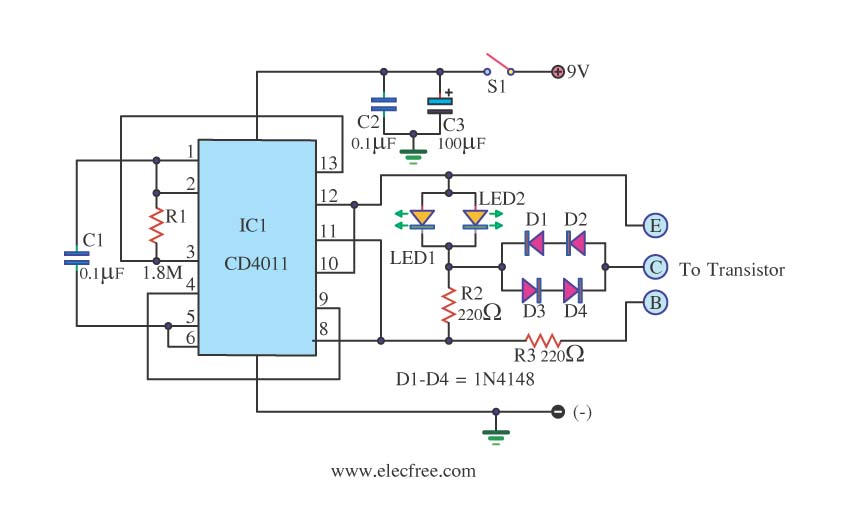
This is a transistor tester integrated into a circuit or printed circuit board (PCB). It is utilized when a project does not function correctly, allowing for the testing of electronic components. The transistor tester is a crucial tool in electronic...
The TDA2549 is a complete intermediate frequency (IF) circuit that includes automatic frequency control (AFC), automatic gain control (AGC), demodulation, and video preamplification capabilities for multistandard television receivers. It can process both positively and negatively modulated video signals in...
The time is set by potentiometer R2, which provides a range from 1 second to 100 seconds, using a timing capacitor C1 of 100 µF. The output at pin 3 is normally low, keeping the relay in the off...
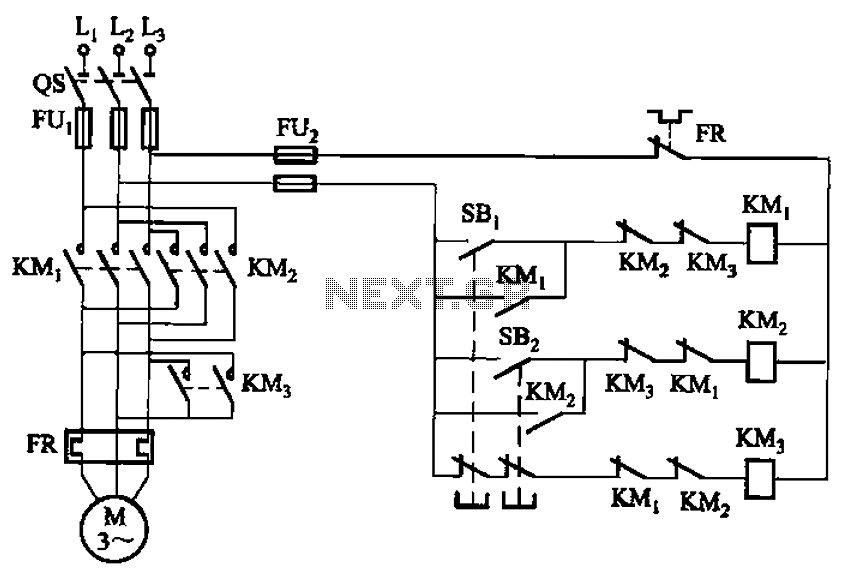
The circuit depicted in Figure 3-154 illustrates the KM3 braking contactors. During shutdown, the system can disconnect the operating system. At this point, KM3 activates, causing its normally open contact to close, thereby shorting the three-phase stator windings to...
A transistor optocoupler interface circuit, as described in section 15.1.6, has been implemented. This circuit serves as a transistor interface with other circuits. The transistor optocoupler interface circuit utilizes a light-emitting diode (LED) and a phototransistor to achieve electrical isolation...