
Solid laser range finder receive circuit diagram

This circuit is designed to achieve high levels of magnification while maintaining a broad frequency response, making it suitable for applications requiring precise signal amplification. The input impedance of 700 ohms allows for effective interfacing with various signal sources, ensuring minimal signal loss during the amplification process. The output impedance of 35 ohms at 5 MHz is optimized for compatibility with standard measurement equipment, facilitating accurate signal analysis.
The use of transistors T1 and T2 as direct coupling amplifiers is crucial for maintaining signal integrity across the amplification stages. Direct coupling minimizes phase shifts and frequency response variations that can occur with capacitive coupling. The implementation of negative current feedback in parallel configuration enhances the linearity and stability of the amplification process, reducing distortion and improving overall performance.
The circuit's bandwidth of 0.5 to 14 MHz indicates its versatility in handling a wide range of signal frequencies, making it applicable in various electronic measurement and testing scenarios. The noise level output of 0.6 to 0.8 V is indicative of the circuit's design efficiency, ensuring that the amplified signal remains distinguishable above the noise floor.
In summary, this circuit represents a sophisticated approach to high-gain signal amplification, characterized by its high magnification factor, broad bandwidth, and carefully designed impedance matching, making it suitable for advanced electronic applications.This circuitry zooms in magnification of 1200000 times, the bandwidth is 0.5~14 Mhzs, the input impedance is 700 ?, the output impedance is 35 ?(to measure in the 5 MHZ), the output level of noise is 0.6~0.8 V. In the chart, T1 and T2 are direct coupling amplifiers, and be current negative feedback in parallel connection.
The promotion of T2`s emitter l.. 🔗 External reference
Related Circuits
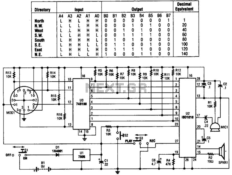
A talking compass consists of a Hall-effect direction sensor (MODI) and an ISD1016 analog audio storage device. It can store eight two-second announcements for each of the eight primary compass directions. The Talking Compass includes a digital compass (MODI),...
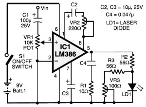
Laser communication system circuit diagram. The circuit module consists of a transmitter and a receiver that utilize the IC LM386. It is powered by a 9V battery. The laser communication system is designed to facilitate wireless data transmission using modulated...

This schematic represents a radio receiver circuit based on the TDA7088T, which is suitable for use in mono portable and pocket radios. The TDA7088T is a bipolar integrated circuit designed to operate with a minimal number of peripheral components...
The only drawback of a single operational amplifier (op-amp) stage is that it inverts the signal, necessitating an additional inverting buffer to restore the original phase if absolute phase is a concern. Various schematics exist for both configurations, but...
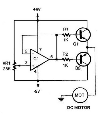
The speed increases in either direction as the potentiometer VR1 is adjusted toward its ends. The TIP3055 Q1 NPN power transistor has a collector current specification of 15A and a VCE0 rating of 60V DC. The MJE34 Q2 PNP...
This circuit controls a small, four-phase, five-wire, unipolar stepper motor, commonly designated as the "KP4M4-001." This type of motor was utilized in many 5 1/4" floppy disk drives in older computers. Although now obsolete, such disk drives are often...