
Solid State Power Controllers

The circuit design incorporates two 555 timer ICs, which are versatile components widely used in various timing, pulse generation, and oscillator applications. The first IC (U1) operates as a variable duty cycle oscillator, allowing for dynamic adjustment of the output signal's duty cycle, which is essential for controlling the power delivered to the load. The duty cycle variation is achieved using a potentiometer (R4), providing user-friendly control over the output power.
The second IC (U2) is configured as a Schmitt trigger, which is advantageous for its noise immunity and ability to provide clean, stable output transitions. The hysteresis in the Schmitt trigger ensures that the output state does not oscillate near the threshold voltage, providing reliable switching behavior.
The transformer (T1) and rectifying diodes (D1 and D2) convert the AC input voltage into a unidirectional form suitable for the control circuitry. The filtering capacitor (C1) smooths out the rectified voltage, ensuring stable operation of the Schmitt trigger. The use of a diode (D3) to prevent filtering across R1 is a critical design choice that maintains the input voltage levels necessary for accurate Schmitt trigger operation.
The triac serves as a power switching device, allowing for efficient control of high-power loads. The design allows for zero-crossing switching, which minimizes electromagnetic interference and reduces stress on the load by turning the triac on and off at the zero voltage crossing points of the AC waveform.
The assembly on a general-purpose IC strip board facilitates ease of construction and prototyping, while the linear potentiometer with a plastic shaft provides a user-friendly interface for power adjustment. Safety considerations, such as ensuring the heat sink does not contact a metallic enclosure, are essential for reliable and safe operation of the circuit. Overall, this circuit exemplifies a practical and efficient approach to controlling AC loads with variable duty cycle switching.The circuit is built around two 555 timer ICs. U1 and U2. U1 is wired as a variable duty cycle oscillator with a constant time period of around 0. 1 second. Duty cycle can be varied from 0 to 100 per cent by R4 potentiometer. The output of U1 (pin 3) is connected to the rest input (pin 4) of U2. U2 is wired as a comparator with hystereis, i. e a Schmitt trigger. Diode D6 brings the potential at control voltage (pin 5) terminal at 0. 7V. The threshold (pin 6) and trigger (pin 2) terminals connected together constitute the input. The output (pin 3) of the Schmitt trigger goes high when Vin equals or below 0. 35V and goes low when it is equals or above 0. 7V. Transformer T1 with rectifying diodes D1 and D2 delivers unidirectional AC voltage across R1 with a peak voltage of 8. 5V and 100Hz frequency. C1 is the filtering capacitor. D3 prevents the voltage across R1 from being filtered. Since the input of the Schmitt trigger is connected across R1, its out put will be high when input voltage falls below 0.
35V and remains so till it exceeds 0. 7V. If pin 4 of U2 is left unconnected, the triac will be fired at the start of each half cycle of AC by a short pulse. Hence full power will be delivered to the load. But since output of U1 is connected to the rest input of U2, the Schmitt trigger delivers pulses to the gate of triac only when output of U1 is high.
This explains how variable duty cycle zero crossover switching is accomplished. I have used a 5-amp triac, which is capable of switching loads up to 1000W. Using a triac with larger current rating can also control higher loads. Of course, size of the heat sink will have to be suitably increased. You can build this circuit in a general purpose IC strip board. Potentiometer R4 should be linear with a plastic shaft. It can be mounted on the front portion of the enclosure, with a dial marked from 0 to 100 per cent power at, say 5 per cent intervals. If a metallic enclosure is used, care must be taken to ensure that the heat sink of triac does not touch it anywhere.
🔗 External reference
Related Circuits
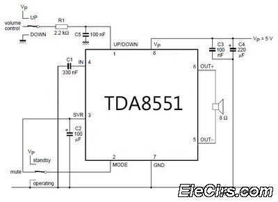
An amplifier with digital volume control can be designed predictably due to the simplicity of the circuit, which utilizes a single chip, the TDA8551. This series of mini amplifiers with digital volume control operates as a BTL (Bridge-Tied Load)...
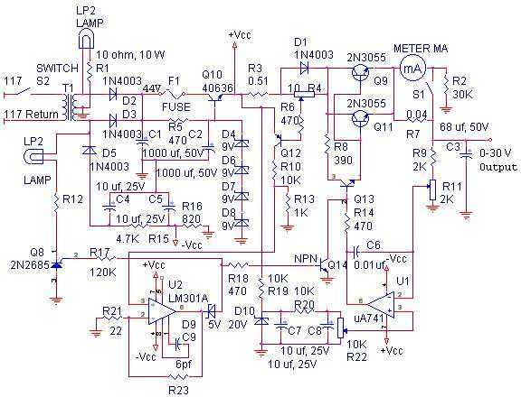
With reference to the schematic, lamp LP2 is a power-on indicator. The other lamp (lower) lights when the unit reaches its preset current limit. R5, C2, and Q10 (TO-3 case) operate as a capacitor multiplier. The 36-volt zener across...
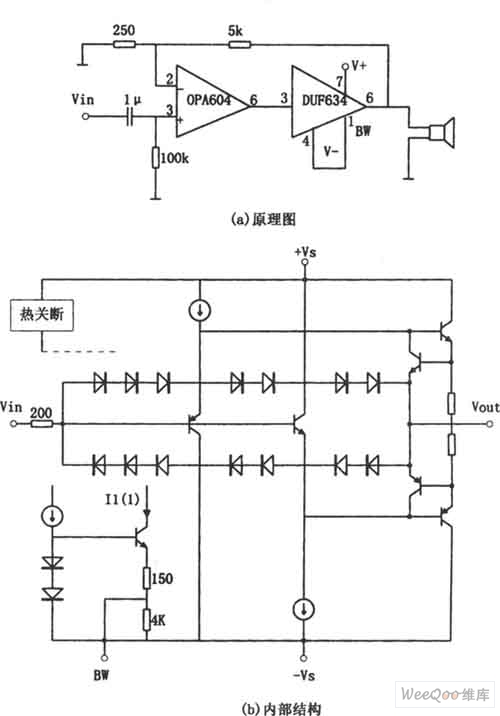
The provided image depicts a high-performance and low-power audio power amplifier circuit. The initial stage utilizes the MOSFET hi-fi operational amplifier OPA604, while the subsequent stage employs the high-speed buffer BUF634. Voltage series negative feedback is implemented between the...
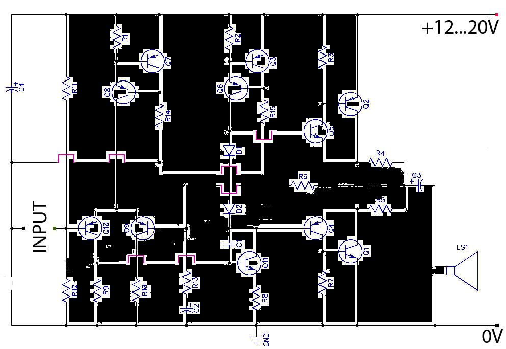
This is a Class AB transistor power amplifier. It is straightforward to construct, utilizing standard components, and is known for its stability and reliability. The entire circuit employs commonly available parts and can be easily assembled on a general-purpose...
MC44BS373CA: PLL Tuned UHF and VHF Audio Video High Integration Modulator MC44BS373CA The MC44BS373CA Audio and Video Modulator is designed for use in VCRs, set-top boxes, and similar devices. Manufactured by Freescale Semiconductor, Inc. The MC44BS373CA is a highly integrated...

This circuit is designed for an LM1893 power line modem, which facilitates information transfer between remote locations using the power mains. The LM1893 serves as a power line interface for half-duplex (bi-directional) communication of serial bit streams employing various...