
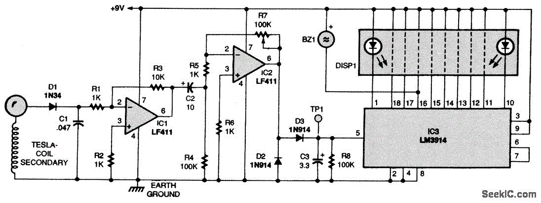
SOLID STATE TESLA COIL

The described Tesla coil circuit utilizes a TV flyback transformer to achieve high-voltage output suitable for various applications. The pulse generator serves as the heart of the circuit, generating a series of pulses that control the operation of the driver circuit. The driver circuit amplifies these pulses to provide sufficient current to drive the flyback transformer.
Resistors R1 and R2 play a crucial role in determining the duty cycle of the output signal. By adjusting these resistors, the user can control how long the output remains off, which directly affects the overall performance of the Tesla coil. R3 and R4 work in conjunction with R1 and R2 to establish the ON time, ensuring that the transformer receives adequate energy during each pulse cycle.
Inductor L1 and regulator IC2 are essential for maintaining a stable voltage supply to the timer circuit, which is critical for consistent operation. The stability provided by these components ensures that the pulse generator can operate reliably, producing a continuous waveform.
Transistor Q1 acts as a buffer to isolate the pulse generator from the flyback transformer, preventing loading effects that could distort the pulse signal. Resistor R6 is strategically placed to control the rise time of the signal, which is influenced by the time constant formed with the gate capacitance of Q3. This careful timing is vital for ensuring that Q3 switches on and off at the correct moments, allowing for efficient energy transfer.
Resistor R8 is a current-limiting component that protects T1's primary winding from excessive current, which could lead to overheating and failure. Capacitor C5 serves a dual purpose; it not only absorbs back EMF from the primary winding but also helps to smooth out voltage spikes, reducing the risk of damage to sensitive components like Q3.
The secondary winding of the flyback transformer generates a high-voltage output characterized by a ringing oscillation. This oscillation is an essential feature of Tesla coil operation, as it allows for the buildup and release of energy. The timing of the ON and OFF states of the pulse train is critical; if synchronized correctly, the secondary winding can produce a nearly constant high-frequency, high-voltage current, which is the desired output for Tesla coil applications.A TV flyback transformer can double as a low-power Tesla coil. The Tesla circuit consists of a pulse generator, a driver circuit, and a high-voltage transformer. Resistors R1 and R2 determine the time duration that the output at pin 3 is off, while R3 and R4 along with R1 and R2 determine the ON time. Inductor L1 and regulator IC2 provide a clean, stable power source for the timer. Transistor Q1 acts as a buffer. Resistor R6 determines the rise time based on the time constant developed by R6 and the inherent gate capacitance of Q3. Resistor R8 limits current so that excessive current will not damage T1`s primary winding. Capacitor C5 absorbs some of the back EMF generated in T1`s primary. The pulse waveform from IC1 is applied to Q1, which provides the high current necessary to offset the high capacitance of Q3.
Capacitor C5 partially absorbs the primary EMF, reducing the stress on Q3. The spike produced in the secondary creates a ringing oscillation. When this oscillation begins to decay, Q3 is once again switched into its ON state. This dumps the energy into C5 and builds the magnetic field in T1. If the timing of both the ON and OFF states of the pulse train is adjusted correctly, the secondary of T1 produces a nearly constant, high-frequency, high-voltage current. 🔗 External reference
Related Circuits
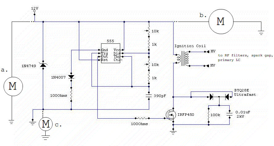
A small DC Tesla coil is being constructed with a rotating spark gap. The motor controlling the rotary spark gap draws approximately 3.8 amps of current at full load, while the 555 control circuit consumes about 4 amps. The...
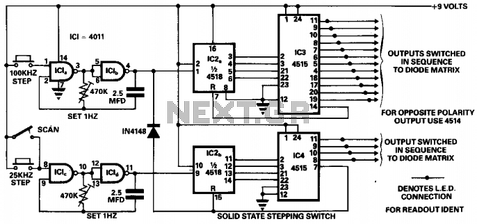
This circuit was designed to ensure safe operation of a 48-channel mobile transceiver while in motion. It incorporates oscillators that facilitate single-stepping or scanning functions. The scanning feature enables the user to sequentially check all 48 channels for occupancy,...
Building a solid-state linear amplifier. An old Heathkit SB 221 has undergone a major overhaul and redesign, and is now functioning well on 80, 40, 20, and 15 meters; however, it does not operate on 17, 12, and 10...
Here is a Tesla coil secondary design: Wind 750 turns of 24-gauge enameled magnet wire onto an 18-inch long piece of 1.9-inch outer-diameter PVC pipe. The large coil has an inductance of approximately 2800 mH and a self-capacitance of...
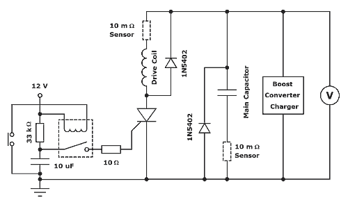
The thyristor-fired coilgun is a prevalent variant, primarily due to its high voltage and pulsed current capabilities. A diagram of the system designed for these experiments is presented in Figure 1. The thyristor utilized is an International Rectifier device,...
This circuit operates effectively from low frequencies up to at least 120 MHz using series resonant crystals in their fundamental or overtone mode. The output can be obtained from the feedback tap, a low impedance winding on L2, or...