
Solid State Triac Relay Schematic

The solid-state relay (SSR) circuit serves as an efficient method for controlling high-voltage loads using low-voltage control signals. It provides electrical isolation between the control side and the load side, enhancing safety in applications where high voltages are involved. The SSR typically consists of an opto-isolator to separate the input control signal from the output load circuit, along with a power semiconductor device, such as a triac or a MOSFET, to switch the load on and off.
In this circuit, the control input is connected to a low-voltage signal, which can be derived from a microcontroller or a switch. When the control signal is activated, the opto-isolator is triggered, allowing current to flow through the output stage. This current activates the power semiconductor, enabling it to conduct and thus energize the load connected to the 120-volt mains.
The design should include protective components, such as fuses or circuit breakers, to safeguard against overcurrent conditions. Additionally, heat sinks may be required to dissipate heat generated by the power semiconductor during operation, ensuring reliable performance and longevity of the relay.
Proper consideration of layout and component ratings is crucial to ensure that the circuit can handle the intended load without exceeding voltage and current specifications. It is also advisable to include snubber circuits or other protection mechanisms to mitigate voltage spikes that may occur when the load is switched off, protecting the SSR from potential damage.
In summary, this solid-state relay circuit is a practical solution for controlling AC loads with low-voltage signals while providing isolation and safety. However, it requires careful design and assembly by qualified individuals to prevent hazards associated with high voltage.This solid state relay circuit uses 120 volts household mains and should only be attempted by someone that has the knowledge and skills to safely construct such a project. Otherwise personal injury and or property damage could result. 🔗 External reference
Related Circuits
In this circuit, a 74HC14 hex Schmitt trigger inverter is used as a square wave oscillator to drive a small signal transistor in a class C amplifier configuration. The oscillator frequency can be either fixed by a crystal or...
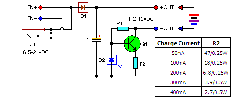
A low-cost solution for charging both NiCd and NiMH batteries is presented. The circuit diagram illustrates a universal charger designed for these battery types. The circuit for the low-cost universal charger for NiCd and NiMH batteries typically incorporates several key...
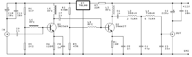
A high-efficiency, simple two-transistor VHF amplifier electronic circuit project can be developed using the provided circuit diagram. This VHF amplifier circuit achieves a significant efficiency with a gain of approximately 16 dB and does not require any tuning or...
Most Tesla coils designed for educational and experimental purposes utilize line-operated, step-up transformer setups to generate the high voltage required for the coil's primary circuit. While this approach is technically sound, it poses a risk to the operator if...
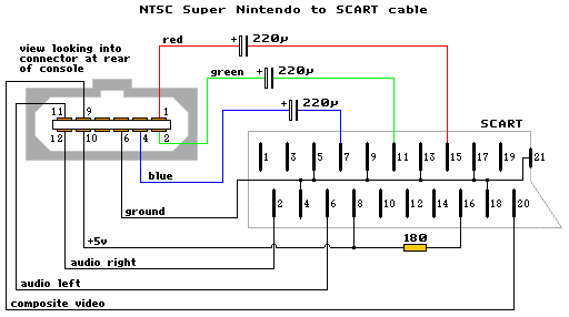
The schematic diagram is similar to the SNES NTSC RGB cable, with the only modification being the addition of capacitors to the RGB line. The diagram is accurate, but it does not include capacitors. A GameCube SCART lead can...
The two circuits below illustrate generating low frequency sinewaves by shifting the phase of the signal through an RC network so that oscillation occurs where the total phase shift is 360 degrees. The transistor circuit on the right produces...