
Solid state voltage indicator with high voltage cutout
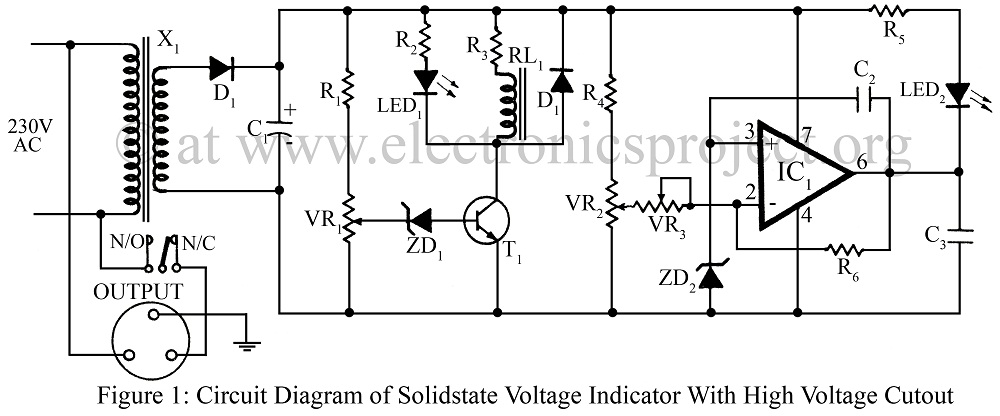
X1 is a voltage step-down transformer that reduces 220V AC to 18V. This voltage is then filtered and rectified by C1 and D1, respectively. Since the output of the transformer is not well filtered and regulated, it remains proportional to the input. VR1 is adjusted to operate the relay at a specific voltage that is higher than the output voltage of the transformer under normal mains conditions. Therefore, when the mains voltage increases, the output of the transformer also rises. The Zener diode ZD2 begins to conduct, providing bias to T1, which in turn energizes the relay and illuminates the RED LED (LED1) to indicate a high voltage. Diode D6 protects the relay against induced voltages.
IC LM741 (IC1) serves as the core of the normal and low voltage indicating circuitry. The potential at the non-inverting input acts as the reference voltage across ZD4. The variable resistor VR3 adjusts the DC gain of IC1. LED D5 is connected between the output (pin 6) and the positive supply, with R5 limiting the current flowing to LED5. Under normal conditions, the voltage at the inverting input is higher than that at the non-inverting input, resulting in a low output, and LED5 remains illuminated. However, when the mains voltage drops, the voltage at the inverting input becomes lower than that at the non-inverting input. Consequently, the output goes high, and the green LED (LED2) turns off. When the IC operates between the upper and lower saturation limits, it functions as a high amplifier, producing a square wave output at pin 6. This square wave causes the green LED (LED2) to blink, indicating low voltage. The frequency of blinking is determined by C2 and R6, and the flashing rate can be adjusted using VR3.
The circuit design effectively combines voltage regulation and monitoring functionalities, making it a cost-effective solution for maintaining the integrity of electronic devices in environments prone to voltage fluctuations. The use of a transformer for voltage stepping, along with rectification and filtering components, ensures that the circuit can accurately respond to changes in mains voltage. The inclusion of Zener diodes for voltage reference and protection enhances the reliability of the circuit, while the operational amplifier (LM741) provides precise voltage comparisons and indications. Overall, this solid-state voltage indicator circuit offers a robust alternative to traditional automatic stabilizers, providing essential protection for valuable electronic equipment.Voltage fluctuations in the mains are very common phenomenon. These fluctuations can cause heavy damage to costly electronics and electrical gadgets operating for long period of time. For such purpose, an automatic stabilizer is used which is usually quite expensive. A costly voltage stabilizer can be replaced with this low-cost Solid-state Voltage Indicator with High Voltage Cutout circuit. It can also be used to convert a manual stabilizer into an automatic one. It performs three functions in different conditions. X1 is a voltage step-down transformer that steps down 220V AC to 18V. This voltage is filtered and rectified by C1 and D1 respectively. As the output of the transformer is not well filtered and regulated, the output will be proportional to the input. VR1 is adjusted to operate the relay at a particular voltage higher than the output voltage of the transformer at normal mains level.
So, when the mains voltage increases, the output of the transformer also increases. Zener diode ZD2 starts conducting and provides bias to T1 which starts conducting. This in turn energizes the relay and light up the RED LED (LED1), to indicate a high voltage. Diode D6 provides protection to the relay against induced voltages. IC LM741 (IC1) forms the heart of the normal and low voltage indicating circuitry. The potential of the non inverting input serves as the reference voltage across zener diode ZD4. Variable resistor VR3 set the DC gain of IC1. LED D5 is connected between the output (pin 6) and the positive supply. R5 limit the current going to diode LED5. Under normal conditions, the voltage as the inverting input will be higher than at the non-inverting input. So the output will be low, ad LED5 will remaining glowing. But, when the mains voltage drops, the voltage at the inverting input becomes lower than that at the non-inverting input.
Thus the output goes high and the green LED (LED2) is extinguished. But when the IC is in between the upper and the lower saturation limits, it will act as a high amplifier and produce a square wave output at pin 6. The square wave will make the green LED (LED2) blink in order to indicate a low voltage. The frequency is set by C2 and R6. The flashing rate can be adjusted by using VR3. 🔗 External reference
Related Circuits

The circuit depicted in the figure includes an automatic voltage regulator (T) that maintains a constant output by utilizing a servo motor. The circuit features transistors VT1 and VT2 (3DK9), with a capacitance range of C (65 ~ 85)....
This application example illustrates a photovoltaic control circuit. In this circuit, the Triac functions as a solid-state relay, providing an AC power supply path to the load. It is designed to achieve high current control signals using a small...
Manual stabilizers remain popular due to their straightforward construction, affordability, and high reliability, as they do not incorporate any relays. Manual stabilizers are widely utilized in various electronic applications, primarily due to their effective voltage regulation capabilities. These devices function...

This multimeter was designed to measure output voltage and current in a PSU, where the current sense shunt resistor is connected in series with load at the negative voltage rail. It needs only one supply voltage that can be...
Monitoring current on inductive loads is a common task. It is easier to perform this on the low side of a driving circuit, as a simple resistor can be used with an operational amplifier on the ground rail. The...
This is a two-state or on/off-type siren where the LM13080 oscillates at an audio frequency and drives an 8-ohm speaker. The LM339 acts as a switch that controls the audio burst rate. The described circuit utilizes the LM13080 integrated circuit,...