
Sophia Electric EL34 Schematic

The schematic in question likely involves a basic amplifier circuit, which may include components such as resistors, capacitors, transistors, and possibly operational amplifiers (op-amps). The primary function of an amplifier is to increase the amplitude of a signal, which can be an audio signal, radio frequency, or any other type of electronic signal.
In a typical amplifier circuit, the input signal is fed into the base or gate of a transistor or op-amp, which then controls the larger current flowing through the collector or drain, effectively amplifying the input signal. Resistors are commonly used for biasing the transistors, ensuring they operate within their active region, while capacitors may be employed for coupling and decoupling signals, as well as for filtering purposes.
Power supply considerations are also critical in amplifier design, as the circuit needs to be powered adequately to handle the required output levels without distortion. The output stage may include additional components to drive speakers or other loads, ensuring that the amplified signal is delivered effectively.
Understanding the role of each component in the circuit and how they interact is essential for mastering amplifier design. This knowledge can be further enhanced by experimenting with different configurations, such as inverting and non-inverting amplifier setups, to observe how changes affect performance parameters like gain, bandwidth, and linearity.I have finally worked out this schematic as an exercise to learn about amps. There are a number of things i am not so sure about and would appreciate.. 🔗 External reference
Related Circuits
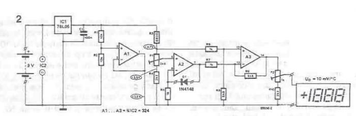
A simple thermometer can be constructed using operational amplifiers and a standard or protective diode, such as the 1N4148, as depicted in the electronic diagram below. A constant reference voltage is supplied to the non-inverting input of the operational...
This is a simple scheme for a bridge oscillator. It provides a nice sinusoidal signal. This type of oscillator uses an op-amp. The weakening of the oscillating member (R1, R2, C1, C2) is 3x. To compensate, the attenuated signal...
This circuit generates a ringing sound similar to that produced by modern telephones. It comprises three nearly identical oscillators connected in a series configuration, each generating a square wave signal. The frequency of each oscillator is determined by the...
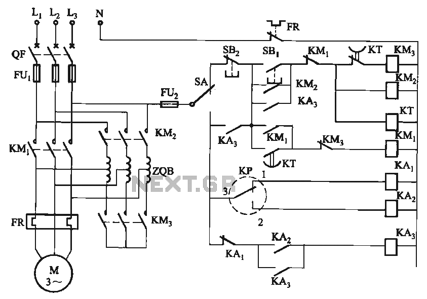
The circuit utilizes a motor auto-voltage transformer for starting. The motor auto-voltage transformer start circuit is designed to provide a controlled method for initiating the operation of an electric motor. This type of circuit is particularly beneficial in applications where...
This power supply unit (PSU) has been designed for high-current ham radio transceivers, providing approximately 20 Amps at 13.8V. It features a secondary output capable of handling currents from 15 mA up to a maximum of 20A. The unit...
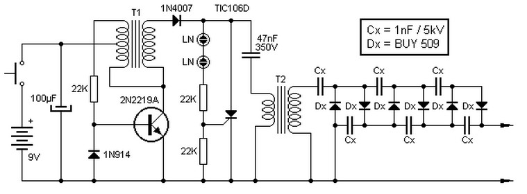
This high voltage source consists of an inverter built around a transistor that generates pulses of 150V. These pulses are supplied to an inverter made of a thyristor and a capacitor, which is connected in series with transformer T2....