
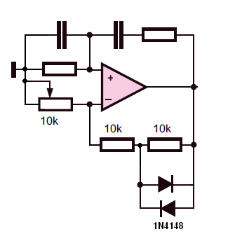
Wien bridge oscillator schematic

C1, C2 = 25V 4.7 µF
C3, C4 = 0.1 µF
R1, R2, R5 = 10 kΩ
R3 = 1 kΩ
R4 = 2.2 kΩ
D1, D2 = 1N4148
IC1 = UA741, LM741
The bridge oscillator circuit described utilizes an operational amplifier (op-amp) to generate a sinusoidal output signal. The configuration is commonly used in signal generation applications due to its simplicity and effectiveness. The op-amp is configured in a feedback loop that allows for the necessary gain to sustain oscillations.
The resistors R1 and R2, along with capacitors C1 and C2, form a frequency-determining network. The combined values of these components will set the oscillation frequency according to the formula:
\[ f = \frac{1}{2\pi R \sqrt{C1 \cdot C2}} \]
where R is the equivalent resistance seen by the capacitors, typically approximated as R1 + R2 in this configuration. The choice of capacitors C1 and C2 at 4.7 µF allows for a sufficient time constant to produce low-frequency oscillations, while the 0.1 µF capacitors C3 and C4 serve as coupling capacitors to stabilize the circuit.
The diodes D1 and D2 (1N4148) are included in the circuit to prevent excessive voltage levels from damaging the op-amp and to help clip the output waveform, ensuring that the output remains within the desired range and maintains a clean sine wave shape. The op-amp IC1 (UA741 or LM741) is a standard choice for this type of application due to its low distortion characteristics and sufficient bandwidth for audio frequencies.
Resistors R3 and R4 are used to set the gain of the op-amp. R3 (1 kΩ) and R4 (2.2 kΩ) work together to provide a gain of approximately 3, which is necessary to compensate for the attenuation introduced by the R1, R2, C1, and C2 network. Resistor R5 (10 kΩ) can be used to provide additional feedback or biasing as needed.
In summary, this bridge oscillator circuit is designed to produce a stable sinusoidal output by utilizing an operational amplifier in conjunction with passive components to define the frequency and shape of the waveform. Proper selection of component values is crucial to achieving the desired oscillation frequency and waveform integrity.This is a simple scheme for whom a bridge oscillator. It provides a nice sinusoidal signal. This type of oscillator uses an op-amp. The weakening of the oscillating member (R1.. .. R2 C1 + C2) is 3x. To compensate, the attenuated signal strengthened.From shall be 3 times the opamp with feedback. To start the oscillation, in the early strengthening higher. Once a certain voltage is reached, the diodes conduct. This will reinforce 3 so that it is not too heavy and not uitdempt sine waves will make. The values ??of R1 + R2 + C1 and C2 together constitute the frequency. C1, C2 = 25V 4?7 C3, C4 = 0.1 uF R1, R2, R5 = 10k ohm R3 = 1k ohm R4 = 2k2 ohms D1, D2 = 1N4148 IC1 = ?A741, LM741 🔗 External reference
Related Circuits
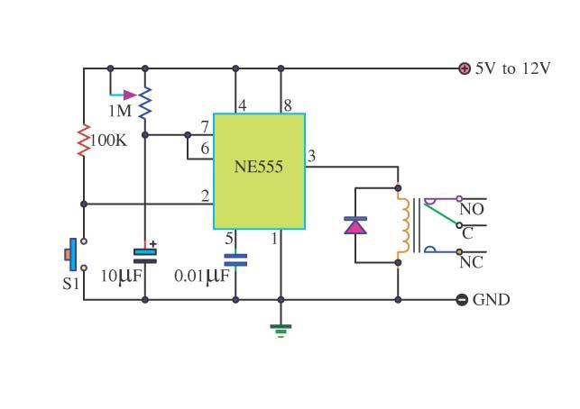
The Simple Timer with a 555 timer is a basic timer circuit that can be utilized in various electronic devices. This circuit leverages the monostable multivibrator mode of the 555 Integrated Circuit (IC). The output control circuit is designed...
Consider using a different operational amplifier. The changes in the input bias current may be causing an unusual voltage drop across the 10k resistors. The LM358 is not a high-quality op-amp, and the diodes in the feedback loop are...
IC1 operates as an oscillator that drives an infrared LED with pulses of 0.8 milliseconds at a frequency of 120 Hz, generating approximately 300 mA of peak current. Diodes D1 and D2 are aligned and positioned a few centimeters...

The complete hardware schematic of the Night Light Saver V6.0 includes an AC line protected by a 1A fuse (F1). Any short circuit caused by the components of the saver will blow the fuse. Resistor R1 and capacitor C1...
This compact amplifier is built around the TDA2003 integrated circuit, which can deliver 4W RMS at a 4-ohm load. The TDA2003 offers enhanced performance while maintaining the same pin configuration as the TDA2002. It retains the advantageous features of...
Unlike conventional small-signal methods, employing large-signal, time-domain design techniques facilitates the development of low-noise grounded-base oscillators suitable for VHF/UHF applications. The implementation of large-signal, time-domain design techniques in the creation of grounded-base oscillators represents a significant advancement in the field...