
sound Circuits

The described circuit utilizes a breadboard layout that facilitates prototyping and experimentation with electronic components. The conductive strips serve as a means of distributing power and ground throughout the circuit, allowing for easy connections to various components. The two long strips along the sides are dedicated to power (+) and ground (-), providing a stable reference voltage for the circuit. The perpendicular rows in the center of the breadboard enable the placement of various electronic components, such as resistors, capacitors, and integrated circuits.
The mention of a potentiometer (or fader) with a resistance range of 0 to 10K or 20K ohms indicates its role in controlling the amplitude of a signal, which is crucial in audio applications. However, caution is advised when setting the potentiometer to its minimum resistance, as this condition creates a short circuit, potentially damaging the LED and other components. The burning plastic smell serves as an indicator of overheating, emphasizing the need for careful handling during experimentation.
The oscillator connection suggests that the circuit may involve signal generation, which is often critical in electronic music applications. Proper orientation of the IC, particularly with the semicircular indentation, ensures correct functionality, as ICs have specific pin configurations that must be adhered to. The unmarked wires indicate that they are used for interconnections, which are essential for establishing the necessary pathways for current flow within the circuit.
The circuit diagram's representation of a NAND Schmitt trigger highlights the logic function of the IC, which is fundamental in digital electronics. This type of circuit is known for its ability to provide clean transitions between high and low states, making it suitable for applications requiring precise timing and signal conditioning. The reference to the datasheet and additional literature on hardware hacking provides valuable resources for understanding the specifications and operational characteristics of the components used in the circuit, enabling further exploration and experimentation in electronic design.This is a slightly less professional-looking version of Handmade Electronic Music, with almost identical content (and free!). See in particular Chapters 18 and 20. Layout of conductive metal strips under the breadboard performations. There are generally two long strips running down each side for power (+) and ground (-) and many rows of perpendicu
lar strips down the middle. Fader hook-up. NOTE: the pot`s resitance varies between 0 and 10K or 20K ohms. If it`s turned down all the way, the circuit will short because there`s no resistance, and the LED will give off a funny burning-plastic smell and stop working (as we discovered in class!). Oscillator hook-up. Orient the IC with reference to the its semicircular intent. Unmarked components are wires. Note the wires at the bottom of the board running power (+) and ground (-) to the long strips on the other side.
Circuit diagram, representing the logic inside the IC (a NAND Schmitt trigger) rather than the IC itself. See the datasheet and "Hardware Hacking" page 75 for more info. The IC ground and power are implied, as is the amp ground. 🔗 External reference
Related Circuits
This sound-activated switch allows for control through sound, which can be beneficial not only in robotics but also in home automation applications. The sound-activated switch operates by detecting specific sound frequencies or patterns, typically using a microphone or a sound...

The doorbell sound circuit produces a two-tone sound. The circuit operates with switch S1. The integrated circuit IC1 functions as a frequency division circuit and generates sound frequencies through components C1 and R1. The audio signal is transmitted from...
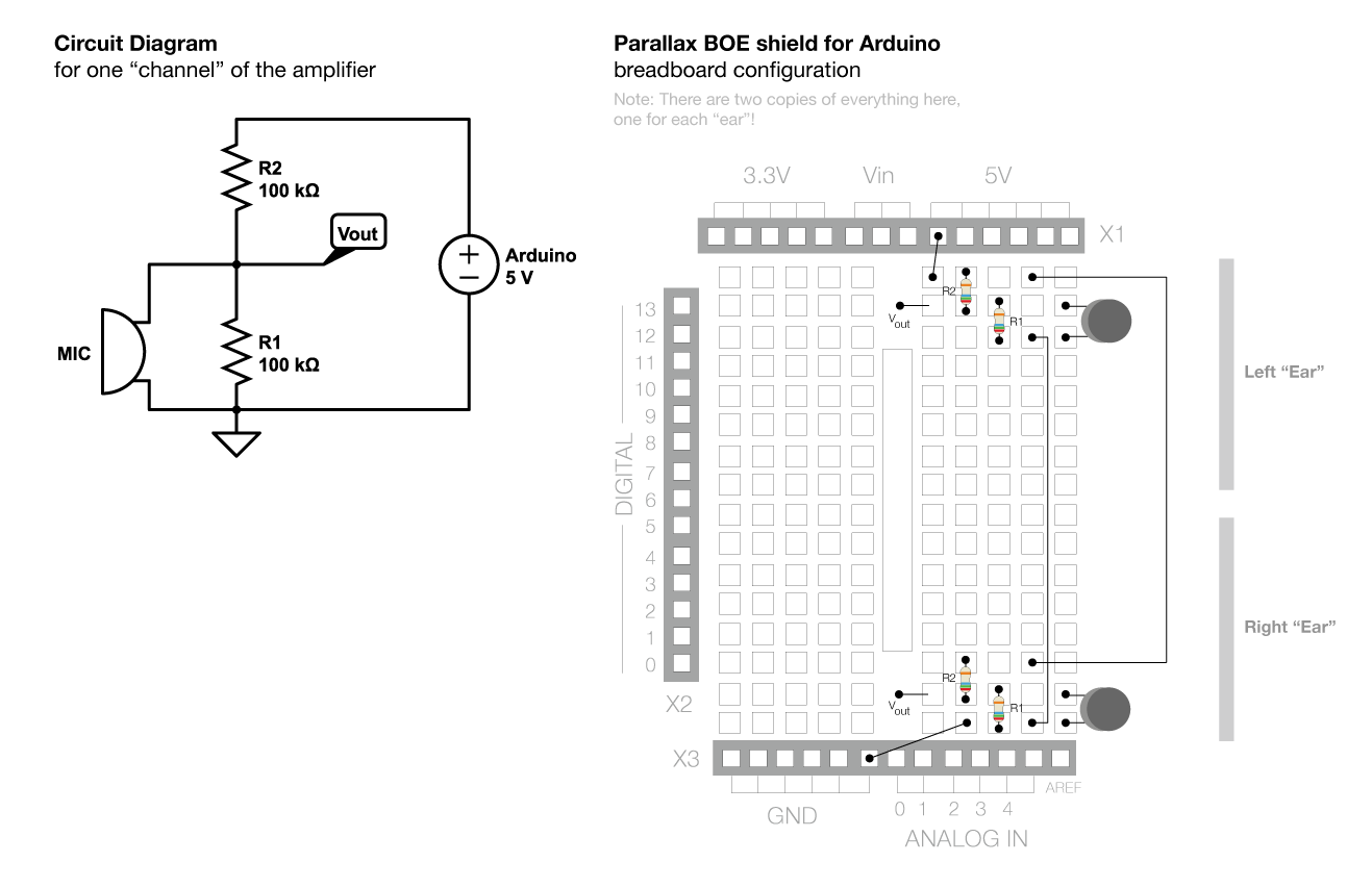
The voltage across the two pins of a microphone fluctuates based on the input sound. To amplify this signal for the Arduino to read it, a complex circuit is required. Initially, the voltage changes from the microphone are small...
This circuit utilizes a single 555 Timer IC along with a small transformer to generate high voltage for testing zener diodes with voltage ratings up to 50VDC. The 555 timer operates in astable mode, with the output from pin...
This is a simple game show timer designed for beginners. The power source can be a standard 12-volt lantern battery or a battery pack made from C or D cells. The lamps used can be regular flashlight bulbs; the...
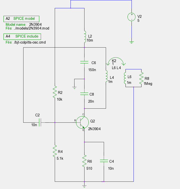
The previous tutorials on SPICE simulation in Fedora Electronic Lab have introduced various concepts. This post focuses on Part 3, assuming familiarity with gschem and completion of a course on analog electronic circuits. It is advised to review the...