
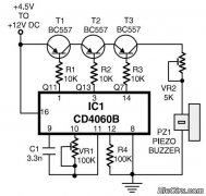
Doorbell Sound with CD4001 CD4060

The doorbell sound circuit is designed to provide a distinct auditory signal through the use of frequency modulation and amplification techniques. The core of the circuit is centered around the frequency division capabilities of IC1, which generates the initial sound frequencies. The interaction between the various integrated circuits (IC2a, IC2b, and IC2c) is crucial for creating the two-tone effect.
IC1, acting as a frequency generator, utilizes the timing components C1 and R1 to define the generated frequencies. The output signals from IC1 are fed into the subsequent stages of the circuit, specifically IC2a and IC2c, which are configured to produce specific tones. The control signal from IC2b plays a pivotal role in determining which frequency is active at any given time, creating the alternating tones characteristic of a doorbell.
The use of output transistors Q1 enhances the audio signal by acting as amplifiers, ensuring that the sound produced is loud enough to be heard clearly. The inclusion of R3 as a variable resistor allows users to adjust the volume, providing flexibility in sound output according to user preference or environmental conditions. Powering the circuit with a 6-volt supply ensures adequate performance while maintaining safety and efficiency for typical doorbell applications.
Overall, this circuit exemplifies effective use of integrated components to achieve a functional and user-friendly doorbell sound system.The doorbell sound circuit was two-tone sound. With the switch S1. working of the circuit, IC1 is a frequency division circuit, and a sound frequency generator came out. by C1, R1 is the frequency generator. This audio signal from pin 7 and pin 4 to pin 1 and pin 8 of the IC2a, IC2c respectively. The IC2b of a frequency converter to control IC2c. Wh en control signal during the low (Low) 1. 25 kHz frequency coincides with IC2a. At same time, the control signal is in a high state IC2b (high), 300 Hz frequency IC2c parties. Output on pin 3 of low IC2a under the same conditions, production and IC2c IC2a IC2d. Which is sent to act as a signal and the output transistors act as switches Q1 and tones amplifiers. The can be heard as two strokes. R3 acts as a volume, add more value to make the softest sound, but softer, a source of 6 volts. 🔗 External reference
Related Circuits
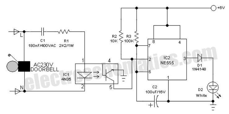
An interesting hobby circuit of a crank doorbell. The circuit is built around a 555 timer and a musical piezo buzzer. It operates using a 9-volt battery supply; a single 9-volt PP3/6F22 compact battery is sufficient to power the...
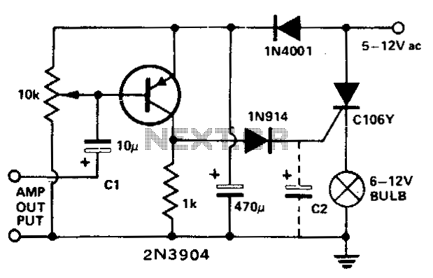
This circuit modulates a light beam using audio signals from an amplifier's output. By adjusting the 10 K potentiometer to a value slightly less than the Vbe of the transistor, the circuit operates as a peak detector. This configuration...
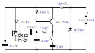
If you wish to take a picture of a fleeting event which generates a sound, you can do it with this sound activated trigger. It does not require any power supply: it feeds on the high voltage available on...
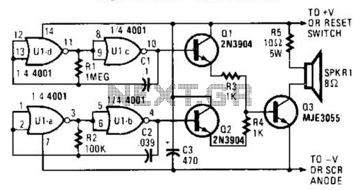
An external horn-type speaker is optimal for this circuit. However, such devices demand significant power, so this sounder should only be employed in alarm circuits utilizing at least a 6-A SCR as the sounder driver. The circuit incorporates a...
This is a simple home telephone ringtone generator circuit constructed using only a few electronic components. It generates a simulated telephone ringtone and requires a DC supply voltage ranging from 4.5V to 12V. This circuit can be used in...
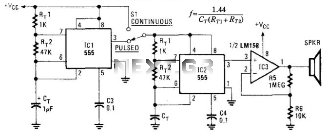
This circuit utilizes two NE555 timer IC devices to generate either pulsed or continuous ultrasonic signals. The values of CT for both pulse rate and ultrasonic frequencies can be calculated accordingly. SPKR refers to a small hi-fi tweeter. The circuit...