
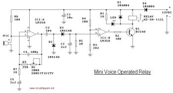
Sound-Controlled Relay

The sound-activated relay circuit typically employs a microphone or a sound sensor to detect audio signals. When sound is detected, the sensor generates a corresponding electrical signal that triggers the relay. The relay, in turn, acts as a switch to control a higher power load, such as lights or other electrical devices.
The circuit generally consists of the following key components:
1. **Microphone or Sound Sensor**: This component captures sound waves and converts them into an electrical signal. Commonly used sensors include electret microphones or sound detection modules.
2. **Amplifier Circuit**: The electrical signal from the microphone is usually weak, so an operational amplifier (op-amp) may be used to boost the signal to a usable level. This amplification ensures that even quiet sounds can be detected reliably.
3. **Comparator**: A comparator circuit can be employed to compare the amplified signal against a predefined threshold. When the sound level exceeds this threshold, the comparator outputs a signal that activates the relay.
4. **Relay**: The relay is a switch that can control a larger load. When activated by the comparator’s output, it closes the circuit, allowing current to flow to the connected device, such as a light bulb.
5. **Power Supply**: The circuit requires a suitable power source to operate the components, which may include a battery or a DC power supply.
6. **Additional Components**: Resistors, capacitors, and diodes may be included in the circuit for biasing, filtering, and protecting against voltage spikes.
The design can be further enhanced by incorporating features such as adjustable sensitivity, delay timers, or even wireless control options. This versatility makes sound-controlled relay circuits suitable for various applications, including home automation systems, security alarms, and assistive technologies for individuals with mobility challenges.This is a relay circuit that detect the presence of sound to activate the relay. You can use this sound-controlled relay as voice operated switch, light. 🔗 External reference
Related Circuits
This circuit diagram illustrates a voice-operated relay, which functions similarly to a sound-activated switch circuit. It activates and deactivates the switch based on sound input. The output switch of this circuit is controlled by a relay. The release time...
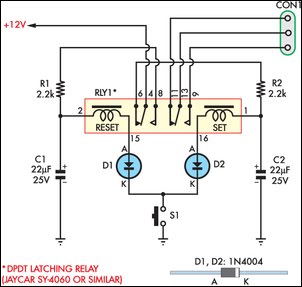
This circuit enables an SPST momentary pushbutton to function as a push-on push-off switch by utilizing a DPDT latching (bi-stable) relay. It was designed to allow a single pushbutton switch on the dashboard of a vintage car to provide...
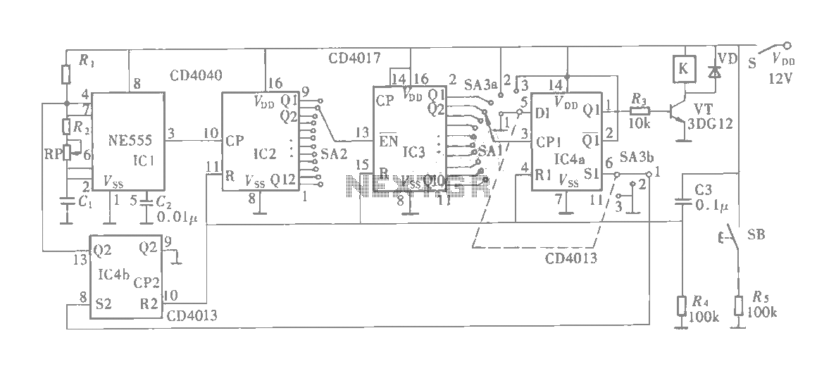
The multifunction circuit primarily refers to its capability to operate in three modes: "delayed pull," "time release," and "delayed cycle." The term "delay" indicates that the relay is energized after a predetermined time; however, the relay does not activate...
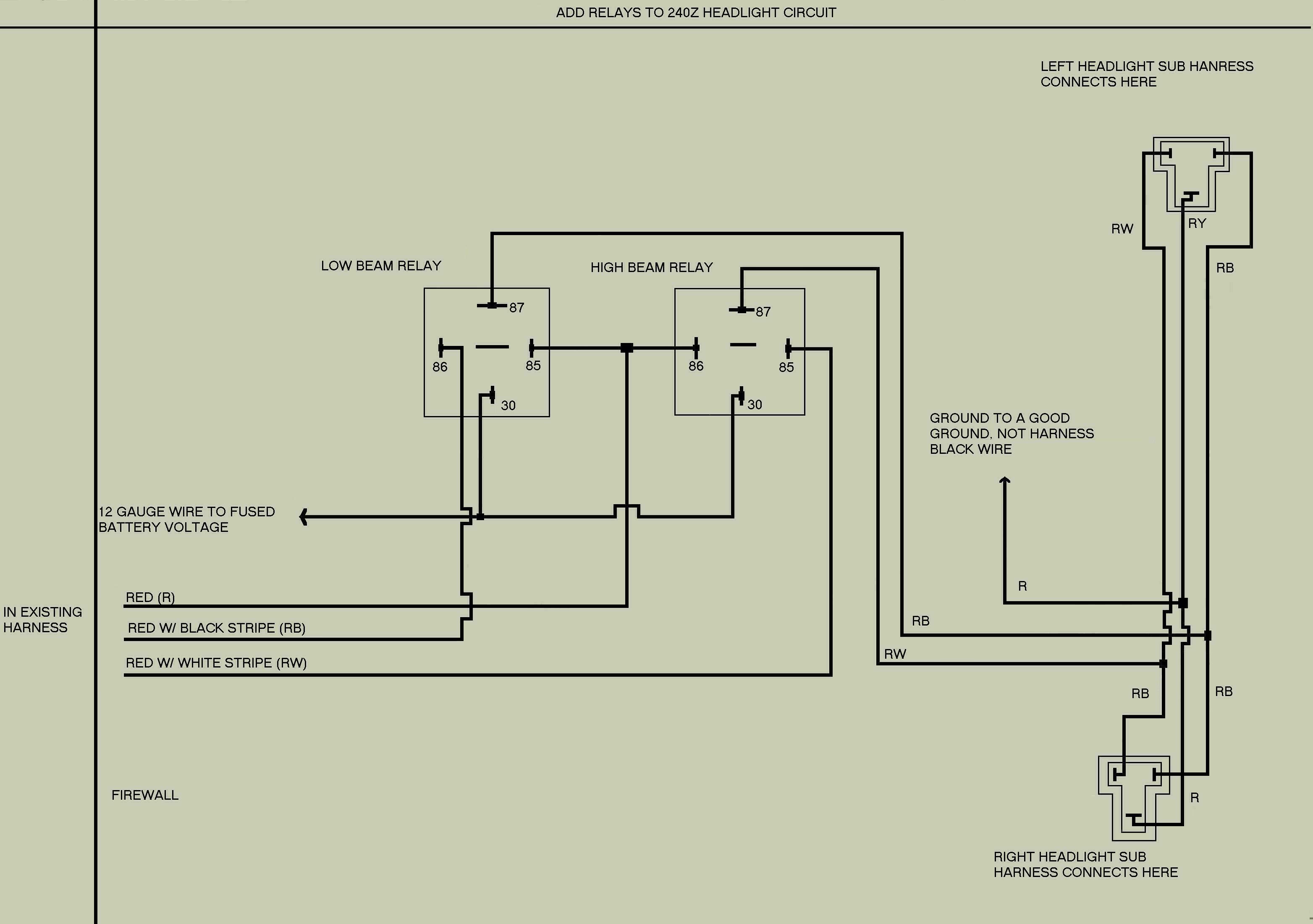
The following is a modification of the headlight wiring for 240Z vehicles. This modification is designed to reduce the current load on the headlight switch by redistributing it to two relays, thereby allowing more current to reach the lights...
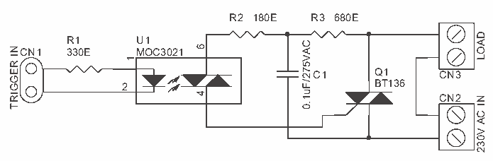
Solid State Relay Switch is a simple kit which will help you control (ON / OFF) a single high power circuit from a low power drive. Load - 24 to 240 VAC @ 500 W. Trigger voltage - 2...
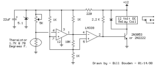
A simple thermostat circuit that can control a relay to supply power to a small space heater through the relay contacts. The relay contacts must be rated above the current requirements for the heater. Temperature changes are detected by...