
240Z Headlight Relay Mod

This headlight wiring modification enhances the performance of the 240Z's lighting system by utilizing relays, which serve as electrically operated switches. By doing so, the modification alleviates the strain on the original headlight switch, which can be prone to wear and failure due to excessive current draw. The relays are typically rated for higher current capacities, allowing them to handle the load more efficiently.
The installation process begins with locating the specified wires in the wiring harness. The T-shaped connector is a critical junction point, and careful identification of the wire colors is essential to ensure proper connections. The wires should be spliced correctly to the relay circuit to maintain functionality. The RB wire should connect to the relay that activates the low beams, while the RW wire should connect to the relay for the high beams. The R and RY wires will be connected to the respective headlight fuses, ensuring that power is supplied to the headlights through the relays.
When implementing this modification, attention must be paid to the relay specifications, including coil voltage and contact ratings, to match the vehicle's electrical system. Additionally, proper insulation and securing of connections are necessary to prevent short circuits or disconnections due to vibrations or environmental factors. This modification not only improves the brightness of the headlights but also enhances the overall reliability of the vehicle's electrical system.The following is my modification of the Headlight wiring for 240Z`s. I made this modification in order to take the current load off of the Headlight switch and put the load onto two relays, giving more current to the lights at the same time. This circuit is intended to be installed by splicing it into the stock 240Z wiring harness on the right fen
derwell. I used wire colors for the 73 240Z, although I believe they are the same for all years. Find the following wires in the harness between the firewall and the connector in front of the radiator support that the right headlight sub-harness plugs into. The connector is T shaped with three male blades in it: The wire on the left is Red with a Black stripe (RB).
In the OE 240Z wiring, this wire is grounded when the low/high beam switch is in the low beam "position". The wire on the right is Red with a White stripe (RW) (on the left headlight). Unfortunately, on the right headlight it is also Red with a Black stripe. From the high/low beam switch it is Red with a White Stripe. In the OE 240Z wiring, this wire is grounded when the low/high beam switch is in the high beam "position".
The wire on the bottom is Red with no stripe (R) on the Right headlight, and Red with Yellow stripe (RY) on the Left headlight. In the OE 240Z wiring, these wires go to the left and right headlight fuses. 🔗 External reference
Related Circuits
Motor Bike Headlight Controller Circuit. This circuit automatically turns a motorcycle's headlight on and off, independently of both the light and ignition switches, provided the battery is fully charged. The first stage... The motorcycle headlight controller circuit is designed to...
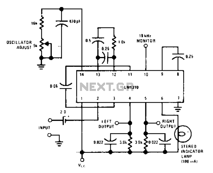
This circuit utilizes a single integrated circuit, the LM1310, to provide left and right outputs from a composite MPX stereo signal. The oscillator adjust resistor R1 is configured for 76 kHz, which corresponds to 19 kHz at pin 10....
This circuit provides a straightforward and efficient method for interfacing two relays in switching applications. The relay driver utilizes a standard BC547 NPN transistor (or equivalent) to enhance the input impedance. It is a widely used driver capable of...
This schematic represents a simple water or liquid level sensor relay switch circuit, designed to control electronic appliances based on water levels. The circuit is particularly useful for automatically turning off a water pump when a water tank, pool,...

Software available on PGM-Fi.org and from Hondata utilizes the Honda ECU's oxygen sensor input to facilitate real-time display and data logging of wideband oxygen sensors. This process involves connecting the analog output from the wideband sensor's controller to the...
Which type of modulated light receiver should be used? A photodiode directly connected to a high-gain, high-impedance amplifier; a photodiode connected to a current amplifier; a back-biased photodiode; FET input or bipolar IC or discrete components? How can noise...