
Sound-Operated Switch

This sound-operated switch circuit is designed to provide a convenient means of activating a lamp in response to the auditory cue of a telephone ringing. The circuit operates on the principle of sound detection and amplification, utilizing a series of components to ensure reliable activation without false triggering.
The input sound signal, generated by the ringing of the phone, is first captured and amplified across resistor R2. This amplified signal is then passed through capacitor C2, which serves to block any DC offset and allow only the AC component of the audio signal to proceed. The diode D1 rectifies the audio signal, converting it into a pulsating DC voltage that provides a negative bias to the base of the PNP transistor Q2. When the audio signal reaches a sufficient level, Q2 turns on, allowing current to flow through to the gate of the silicon-controlled rectifier SCR1.
The SCR1 is a crucial component in this circuit, as it acts as a switch that controls the lamp's power. When triggered by the current from Q2, SCR1 will remain conductive even after the triggering signal is removed, thus keeping the lamp illuminated until the circuit is reset or power is interrupted.
Potentiometer R4 is an adjustable resistor that allows the user to set the sensitivity of the sound detection circuit. By tuning R4, the threshold at which the circuit responds to the sound can be modified, accommodating different environments or user preferences.
To further enhance the reliability of the circuit, resistor R3 and capacitor C3 are employed to create a delay in the activation of transistor Q1. This delay ensures that transient sounds, such as those generated by the on/off switch S1 or unexpected current surges, do not inadvertently trigger the lamp. The combination of R3 and C3 can be adjusted to fine-tune the response time of the circuit, ensuring that only the intended sound (the phone ringing) activates the lamp.
For optimal performance, the lamp should be positioned on top of a TV receiver, and the sensitivity should be adjusted so that a finger snap from a distance of about two feet can successfully trigger the lamp. Additionally, placing the speaker close to the telephone enhances the detection capability, ensuring that the sound of the ringing phone is effectively captured by the circuit. This design offers a practical and innovative solution for alerting individuals to incoming calls, particularly in settings where visual cues may be overlooked. This sound-operated switch will sense the ring of the phone and translate this to a lamp that will go on and off. The amplified signal across R2 reaches D1 through capacitor C2. The rectified audio signals provide a negative bias for Q2, a pnp transistor. This causes Q2 to conduct so the current that triggers SCR1 is provided at the gate. Potentiometer R4 sets the sensitivity. R3 and C3 delay the operating voltage for Ql so that the circuit will not be triggered on by the sound of the on/off switch, SI or by the current surge. Set the lamp atop a TV receiver, turn it on and set the potentiometer so that a finger snap at two feet will trigger the lamp on.
Place the speaker close to the telephone and give it a try. 🔗 External reference
Related Circuits

This system uses a transmitter operating at approximately 100 kHz to control a remote receiver. A line splitter can connect the transmitter to the active telephone line. The transmitter is a CMOS oscillator equipped with output buffer stages to...
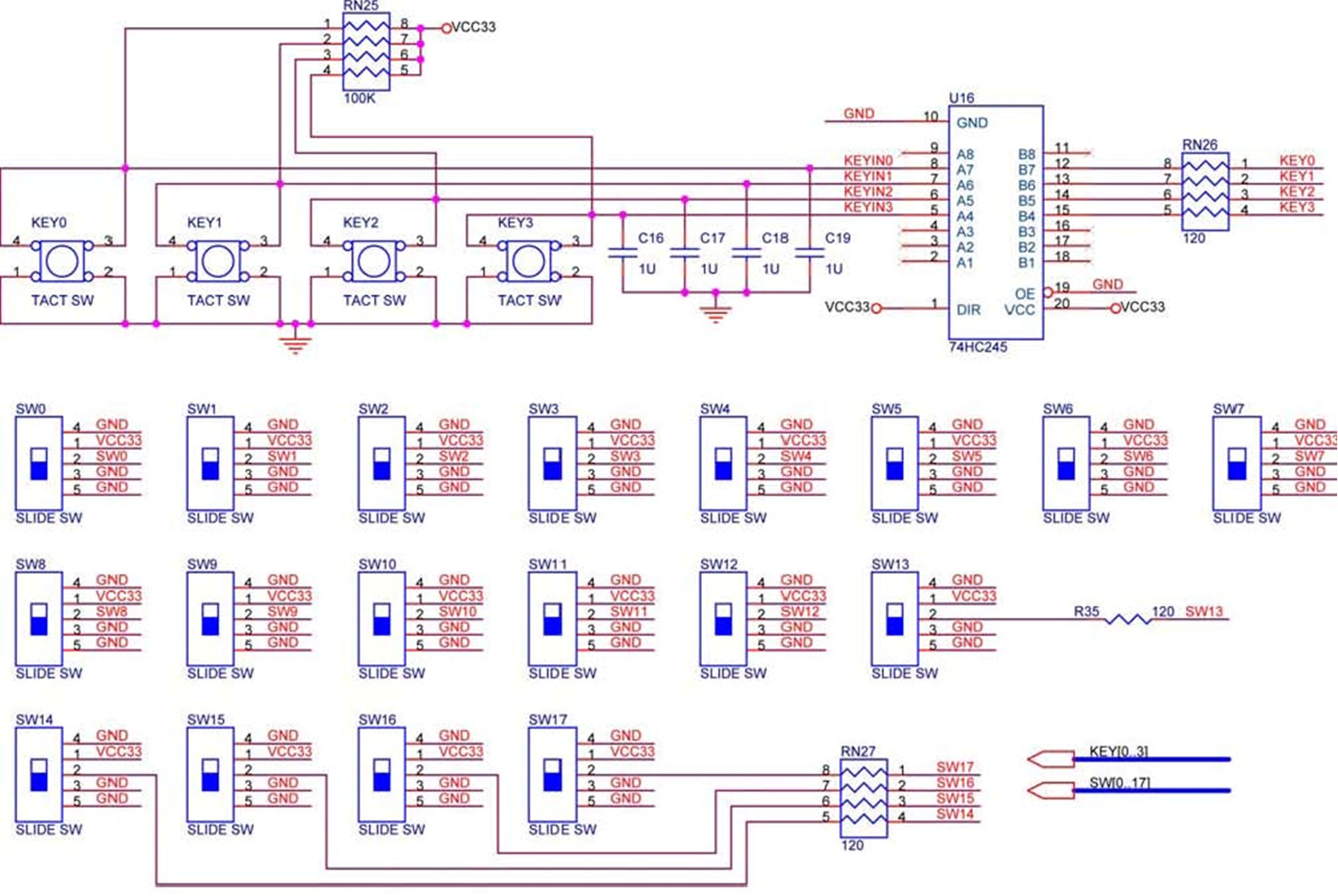
The DE2 board features four pushbutton switches, each of which is debounced using a Schmitt Trigger circuit, as shown in Figure 1. The outputs, labeled KEY0 to KEY3, from the Schmitt Trigger are directly connected to the Cyclone II...
Is there a way to automatically turn on an LED when it gets dark? A version was created using a relay and photoresistor that functioned properly, but concerns arose regarding potential battery drain. The project aims to integrate with...

This touch sensor switch is designed using inverters (N1, N2) and several common electronic components. In the standby state, a signal is produced by the oscillator N3/N4 at the inputs of N1. When the touch sensor is activated, the...
This straightforward circuit can be integrated into a headlight switch to enable automatic switching between high and low beam headlights when there is oncoming traffic. It is a simple electronics project accompanied by a circuit diagram. The circuit operates by...
Model railroad turnouts, often referred to as switches, can be controlled in various ways. The simplest method is manual control, operated by hand. Remote activation is typically achieved through pneumatic (air) or electrical means. The project discussed in these...
Warning: include(partials/cookie-banner.php): Failed to open stream: Permission denied in /var/www/html/nextgr/view-circuit.php on line 713
Warning: include(): Failed opening 'partials/cookie-banner.php' for inclusion (include_path='.:/usr/share/php') in /var/www/html/nextgr/view-circuit.php on line 713