
Sound Operated Switch

The circuit described is a sound-operated switch utilizing a microphone as the input sensor. It can accommodate both dynamic and electret microphones, with a specific resistor (R1) required for the electret configuration to ensure proper operation. A resistor value between 2.2kΩ and 10kΩ is recommended for optimal performance, allowing for flexibility in sensitivity adjustments based on the microphone used.
The audio preamplifier stage consists of two BC109C transistors configured in a cascade arrangement to achieve a desired gain. The gain of the preamp is adjustable via a 10kΩ potentiometer, which allows for fine-tuning based on the environmental noise levels and the specific application requirements. This stage is crucial as it amplifies the low-level audio signals from the microphone to a usable level for further processing.
Following the preamplification, a BC182B transistor is employed to provide additional amplification, ensuring that the output signal is sufficiently strong for triggering the switch mechanism. To maintain stability within the circuit and prevent oscillations, a decoupling network consisting of a 100μF capacitor and a 1kΩ resistor is integrated into the preamp stage. This decoupling arrangement filters out high-frequency noise and stabilizes the power supply to the transistors, enhancing overall circuit reliability.
The output stage will typically interface with a relay or a similar switching device that can be controlled by the amplified audio signal. The entire assembly is designed to be sensitive to sound, allowing for activation by speech or other audio signals, making it suitable for various applications such as automatic lighting controls, sound-activated devices, or remote control systems. Proper layout and component selection are essential to ensure the circuit operates effectively within its intended environment.This sensitive sound operated switch can be used with a dynamic microphone insert as above, or be used with an electret (ECM) microphone. If an ECM is used then R1 (shown dotted) will need to be included. A suitable value would be between 2.2k and 10kohms. The two BC109C transitors form an audio preamp, the gain of which is controlled by the 10k preset. The output is further amplified by a BC182B transistor. To prevent instability the preamp is decoupled with a 100u capacitor and 1k resistor. The audio v 🔗 External reference
Related Circuits
The Zero Volt Diode (ZVD) is a circuit useful in various applications, including solar chargers of all types. It is a novel circuit where a power MOSFET functions as a very low voltage drop diode, switching states at 0V...
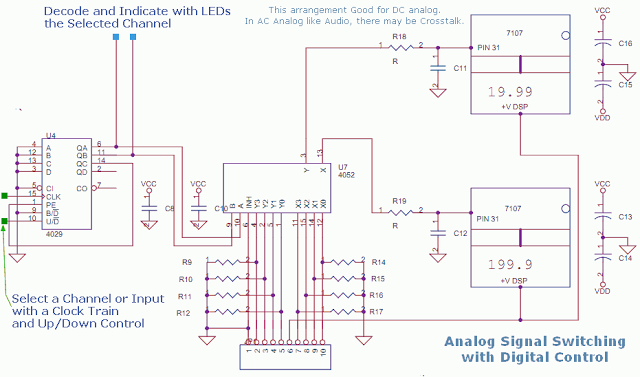
This circuit utilizes a 4052 as a DC Analog Multiplexer. The inputs to this multiplexer must originate from low-impedance output operational amplifiers (OpAmps). The resistors depicted are unnecessary once the signal conditioning OpAmps are connected. However, 100K resistors can...
The DTMF codec stands for dual-tone multi-frequency codec. The multiple-channel infrared remote control switch circuit that incorporates the DTMF is depicted in the figure. It consists of an infrared remote control signal emitter, an infrared receiving signal amplifier, a...
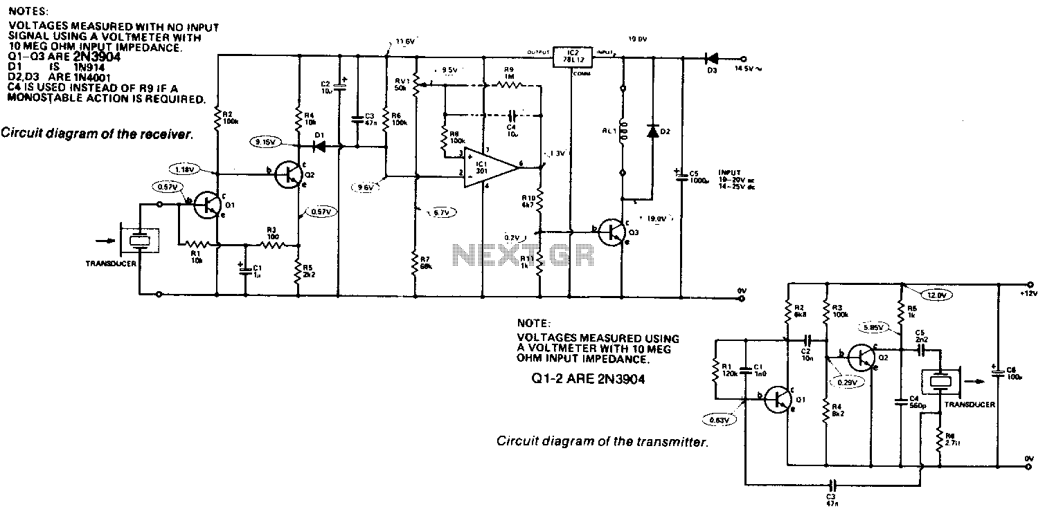
Receiver. The output from the transducer is amplified by Q1 and Q2, and rectified by D1. The voltage on pin 2 of IC1 will become more negative as the input signal increases. IC1 is utilized as a comparator, comparing...
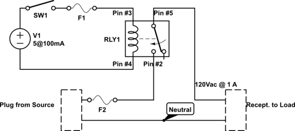
A single-pole double-throw (SPDT) switch is used to control a relay. When the relay is energized, it produces a cycling sound, which is undesirable. The goal is to have the switch operate normally in the 'on' position and return...
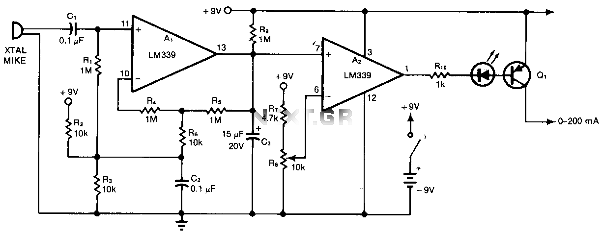
Al and A2 are two sections of a quad comparator. The first section, Al, functions as an amplifier and detector. Resistors R5 and R6 set the gain at 100; the output of Al is an open collector to negative-peak-rectify...