
Soundbar Design From Start To Finish: Clocks Clocks Clocks

The clock design in digital circuits, particularly in soundbar applications, plays a crucial role in ensuring synchronized operation of various components. A clock signal is essential for timing control, data transfer, and overall system performance. In soundbars, which often integrate multiple digital signal processors (DSPs), audio codecs, and other digital devices, precise clocking is vital for maintaining audio quality and minimizing latency.
The clock circuit typically consists of a crystal oscillator, which generates a stable frequency signal, and may include dividers or phase-locked loops (PLLs) to derive additional clock frequencies required by different components. The choice of the oscillator frequency is determined by the requirements of the digital components in use, ensuring compatibility and optimal performance.
Furthermore, the layout of the clock circuit within the PCB design must be carefully considered to minimize noise and interference. Proper grounding techniques, short trace lengths, and adequate decoupling capacitors are essential to ensure signal integrity. Additionally, the use of differential signaling for clock lines can further enhance performance by reducing electromagnetic interference.
In summary, effective clock design in the digital section of soundbar circuits is fundamental for achieving high-quality audio reproduction and reliable operation of the system.TI`s Dafydd Roche completes his 4-part series on sound-bar design with a detailed explanation of clock design for the digital portion of the circuit 🔗 External reference
Related Circuits
Irisys offers a selection of five thermal imaging temperature sensors that utilize a 16G—16 pixel array, providing various options for temperature range, accuracy, and measurement angle. The IRI 1041, IRI 1051, and IRI 1061 models are identical to the...

The circuit diagram illustrates a simple stepper motor controller utilizing basic components. The driver circuit employs four SL100 transistors to control the motor windings, along with two NOT gates and one XOR gate to decode the two-bit control logic...
This circuit replicates the starting light sequence currently utilized by FISA for Formula One racing. It can be applied to slot car sets (such as HO scale AFX/Life Like/Tyco sets) or radio-controlled cars. IC1, a 555 timer integrated circuit,...
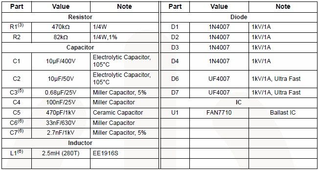
The FAN7710 Ballast Control IC for Compact Fluorescent Lamps, developed using Fairchild's unique high-voltage process and system-in-package (SiP) concept, enables the design of a simple and low-cost fluorescent lamp driver electronic project. The FAN7710 ballast control manages internal high-voltage...
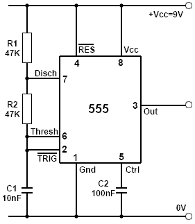
If an oscillator of a specific frequency and mark-to-space ratio is needed, the periodic time can be calculated from the required frequency, as well as the discharge and charge times using the formulas for tD and tC outlined in...
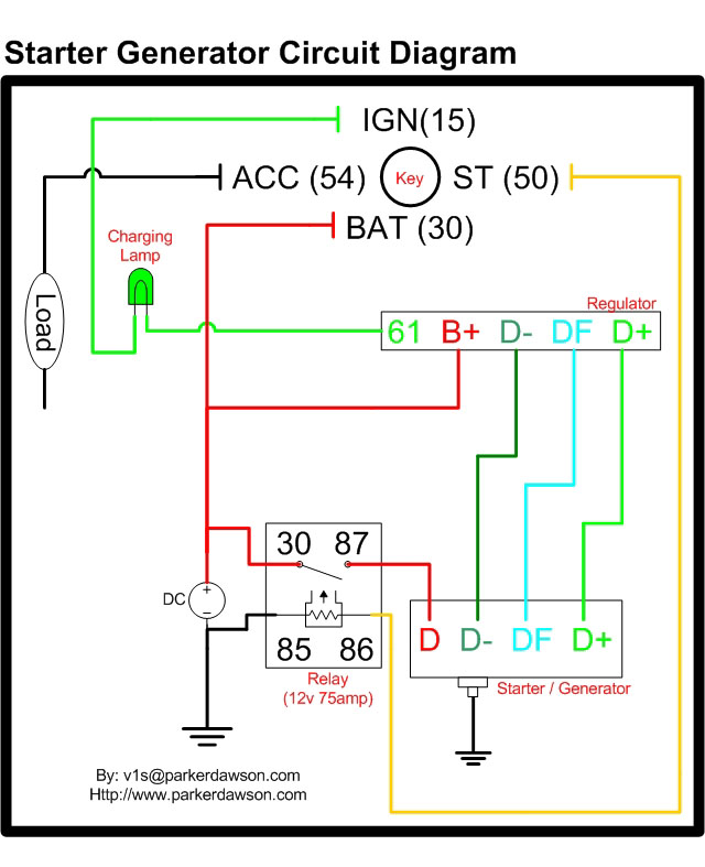
Circuit diagrams for both a Bosch and a Delco-Remy Starter-Generator are available, noting that the circuits differ. Due to a computer crash, the original diagrams and the associated email address were lost. However, in May 2004, both the email...