
Stepper motor controller - Driver circuit with circuit design

The circuit operates by using a four-transistor configuration to sequentially energize the stepper motor windings, allowing for precise control of the motor's position and movement. The transistors function as switches that control the current flow through the motor coils, enabling the motor to step in discrete increments. The NOT gates and XOR gate serve as logic elements that interpret the control signals, ensuring that the correct combination of transistors is activated for the desired stepping sequence.
The 555 timer in astable mode generates a continuous square wave output that acts as a clock signal for the up/down counter. This configuration allows the user to set the desired speed of rotation by adjusting the frequency of the 555 timer, which directly influences the stepping rate of the motor. The up/down counter can be configured to count in either direction, thereby facilitating both clockwise and counterclockwise motor rotation.
The diodes D1 to D4 play a crucial role in protecting the transistors from back EMF generated when the motor windings are switched off. This transient voltage can damage the transistors if not properly managed, making the inclusion of these protective diodes essential for the longevity and reliability of the circuit.
Power supply considerations are also important; the Vcc voltage must be selected based on the specific requirements of the stepper motor being used. While the circuit can accommodate motors rated up to 24V, higher voltage applications necessitate the use of transistors capable of handling the increased power levels, such as the 2N3055, which offers greater current and voltage ratings than the SL100.
Overall, this stepper motor controller circuit is a versatile solution for applications requiring precise motor control, leveraging simple components to achieve effective performance in driving stepper motors.Here is the circuit diagram of a simple stepper motor controller using only elementary parts. The driver circuit uses, four transistor (SL100) to drive the motor windings, two NOT gates and one XOR gate to decode the two bit control logic to drive the four windings of the motor. The diodes D1 to D4 protects the corresponding transistors from trans ients generated during the switching of motor windings. d0 and d1 are the control logics which determines the direction of rotation as well as speed. The control logic for the circuit can be obtained from a 2 bit up/down counter clocked by a 555 astable multivibrator. The direction of count determines the direction of rotation and the frequency of astable multivibrator determines the speed of rotation.
Vcc is the voltage required for the stepper motor. It varies from motor to motor. Here we can use up to 24V stepper motors. For higher operating voltages and power the SL100 transistors must be replaced with higher power transistors like 2N3055. 🔗 External reference
Related Circuits

This circuit can be used to drive a 12V relay with a triggering signal of 5V. It incorporates two 1N4002 diodes, one 2N3904 transistor, and two resistors. By altering the resistor values, the input triggering voltage can be modified. The...
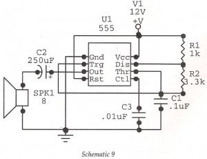
This circuit features an astable oscillator constructed around a 555 timer, generating an alarm tone of 1.8 kHz, which directly drives a speaker. It serves as a fundamental alarm circuit that can be utilized in various projects. Although the...

This is a simple mini audio amplifier circuit built around a single LM383 integrated circuit, along with several discrete components to support its operation. The circuit is capable of delivering approximately 7W of audio output. It can be constructed...
The Xminilab-B oscilloscope is based on the Atmel AVR ATXMEGA32A4 microcontroller. It is designed as a debug board by the Gabotronis company, as noted on rlocman.ru. The Xminilab-B oscilloscope features a compact and efficient design that leverages the capabilities of...

This project shows you how to build a relay controller using the Basic Stamp I interfaced to the PC serial port. The Visual Basic 5 software developed for the interface lets you interact with the Basic Stamp to turn...
A motor driver is required in pretty much all walkers including all of my CW series walkers. You need to use it any time you need to supply more current to the motors because the circuit can't supply enough....