
Speaker Microphone Circuit

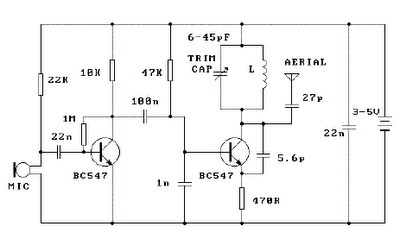
The circuit utilizes a basic configuration to convert sound waves into electrical signals effectively. The first stage, featuring a transistor in a common base configuration, serves to amplify the small signals generated by the loudspeaker. This configuration is particularly advantageous because it allows for a direct connection to the low-impedance output of the loudspeaker, ensuring optimal signal transfer. The common base stage is known for its high voltage gain, which is crucial for enhancing the weak signals produced by the speaker.
Following this initial amplification, the second stage of the circuit employs an emitter follower configuration. This stage is characterized by its ability to provide a low output impedance, which is essential for driving longer cable runs without significant signal degradation. Although the voltage gain in this stage is slightly less than one, the benefits of low output impedance and the ability to drive external loads make it a valuable addition to the circuit.
The design accommodates a variety of loudspeakers, with the flexibility to handle cone sizes from 1 inch to 3 inches and impedances from 4 ohms to 64 ohms. This versatility allows for the use of different speaker types, making the circuit adaptable for various applications. The inclusion of an adjustable resistor (8.2 ohms) provides further customization, enabling users to match the circuit to the specific characteristics of the loudspeaker in use.
While the audio quality produced by this circuit may not rival that of higher-end microphones, it is sufficient for many applications, particularly where cost-effectiveness is a priority. This circuit is suitable for hobbyist projects, basic audio recording, or other scenarios where a simple and low-cost microphone solution is desired.This circuits allows you to use a cheap loudspeaker as a microphone. Sound waves reaching the speaker cone cause fluctuations in the voice coil. The voice coil moving in the speakers magnetic field will produce a small electrical signal. The circuit is designed to be used with an operating voltage between 6 and 12 volts dc. The first transistor op erates in common base mode. This has the advantage of matching the low input impedance of the speaker to the common base stage, and secondly has a high voltage gain. The second stage is direct coupled and operates in emitter follower. Voltage gain is slightly less than unity, but output impedance is low, and will drive long cables. Speech quality is not as good compared to an ordinary or ECM microphone, but quite acceptable results can be obtained.
Speaker cones with diameters of 1 inch to 3 inches may be used. Speaker impedance may be 4 ohm to 64 ohm. The 8. 2 ohm resistor value may be changed to match the actual speakers own impedance. 🔗 External reference
Related Circuits
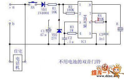
Utilize the 48V (60V) DC feedback electric current supplied by the phone feedback line as the operational energy source for the electronic doorbell, which is highly economical and practical. This document introduces a two-tone doorbell circuit that operates without...
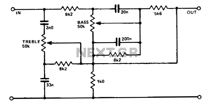
A simple circuit using two potentiometers and easily available standard value components provides tone control. The impedance level is suitable for low-level transistor or op-amp circuitry. This tone control circuit typically employs two potentiometers to adjust the bass and treble...
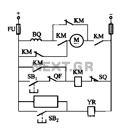
The DW16M-630 type excitation switch operates with both DC and AC power. The circuit for DC operation is illustrated in Figure 7-60, while the circuit for AC operation is shown in Figure 7-61. The BQ single-phase series motor M...
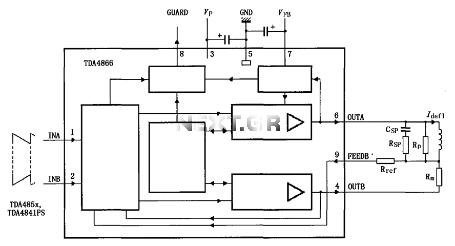
The TDA4866 is a 90-color power amplifier designed for vertical deflection systems, operating at a frequency range of 50 to 160 Hz. The CRMM circuit is implemented to ensure a high current drive input. The amplifier features a dual...
It is essential to consider migrating to PIC microcontrollers and exploring compilers such as those offered by Proton Smart, which include Sony IR and Philips RC5 codecs. This approach is particularly advisable for security-sensitive applications. Additionally, Bluetooth and Wi-Fi...
Place the transmitter approximately 10 feet away from an FM radio. Set the radio to a frequency between 89 and 90 MHz. Walk back to the FM transmitter and turn it on. Separate the windings of the coil by...