
Speech Board for SPO256


Design goals include a compact board size (hence the nested chips), minimal control lines (four), various construction options, and a high-quality circuit board. The layout was designed using ExpressPCB software. The board is double-sided, drilled, and solder reflowed, featuring four mounting holes at the corners, a solder mask, and silk-screening. The dimensions are approximately 1.5 inches by 2.5 inches (about 3.8 cm by 6.4 cm), with a densely packed design that places the shift register beneath the socket for the SPO-256. The bits are clocked out from the least significant bit (LSB) to the most significant bit (MSB). This board requires a moderate level of soldering proficiency and a fine soldering iron. It employs a shift register to convert serial input (not RS232 serial) to parallel for the SPO256, requiring only four control lines: C - CLK for the shift register (pin 0 in the circuit), I - INA for the shift register (pin 1), A - ALD allophone load for the SPO256 (pin 2), and L - LRQ for the SPO256 (pin 3).This board does NOT use the CTS256AL2 text-to-speech chip. [It would seem that both SpeechChips.com and JDR still have some of these chips, though, if you're looking for some.] However, you could easily use this board to hold the SPO chip and amplifier and connect it to your own CTS circuit. All necessary pin connections do have an available solder pad for off-board connections. Additionally, there is a socket for a 12C508/9 PIC which can reduce control pin count down to 2, or even to 1.
This would also allow the line-twiddling to be offloaded from the Stamp or whatever else is the master controller. I've done the bulk of the code with some debugging and fine-tuning left. Both the PIC and audio amp [LM386] are optional and there is a provision for adding either an LED on-indicator OR a separate power supply for the amp.
Amp gain is 200 and seems to be adequate with 5v supply. There is some room for a trimmer cap for the crystal in case your SPO256 chip is overly sensitive to the clock stability [as one of mine is]. The board can also be fitted with a 5v voltage regulator if you can't provide it with a regulated supply.
But this option is not recommended. Design goals: Small board size [hence the nested chips] Few control lines [4] Some construction options High quality circuit board Layed out with ExpressPCB s/w. [Visit Express PCB site (Manufacturing Specifications for Production Service) for more information about their product.] Double-sided, drilled, solder reflowed 4 mounting holes on corners solder mask silk screen.
Pretty small [1.5" x 2.5" (ca. 3.8 cm x 6.4 cm)] and fairly densely packed the shift register is UNDER the socket for the SPO-256 bits are clocked out from LSB to MSB This board equires a moderate level of soldering proficiency and a fine soldering iron. Uses shift register to convert serial input [NOT RS232 serial] to parallel for SPO256. Only requires 4 lines to control: C - CLK for shift register [pin 0 in circuit below] I - INA for shift register [pin 1] A - ALD allophone load for SPO256 [pin 2] L - LRQ for SPO256 [pin 3]
🔗 External reference
Related Circuits
CPU NatSemi Geode operating at frequencies of 200/233/266/300 MHz (with a default speed of 233 MHz on-board) or refer to the Geode link. The VGA/LCD interface is NS GX5530, featuring shared memory of 2.5MB, supporting CRT displays and 18-bit...
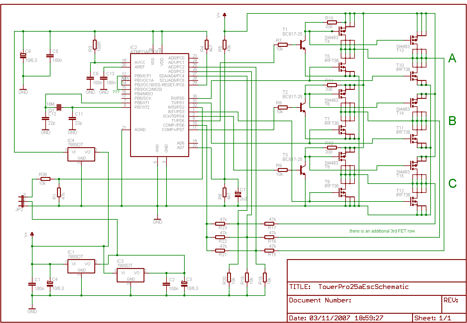
Is it feasible to eliminate the Electronic Speed Controllers (ESCs) from a multicopter configuration and substitute them with a single circuit board to control all the motors? The current setup consists of eight motors, each requiring an individual ESC,...
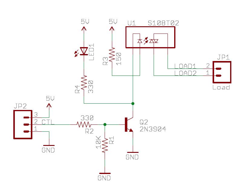
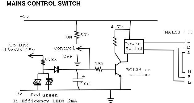
The Sparkfun Solid State Relay (SSR) Breakout Board operates similarly to a traditional relay but utilizes semiconductors for switching. It is powered by the mbed VU 5V supply and is compatible with any mbed digital output pin. The schematic...
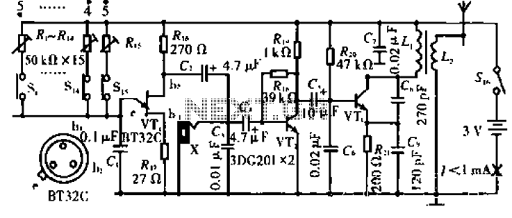
The circuit operates with VT3 and associated components arranged as a common-base capacitance feedback oscillation circuit. The oscillation frequency is set by capacitors C8, C9, and inductor L1. VT2 serves as a voltage amplification stage that reinjects the audio...
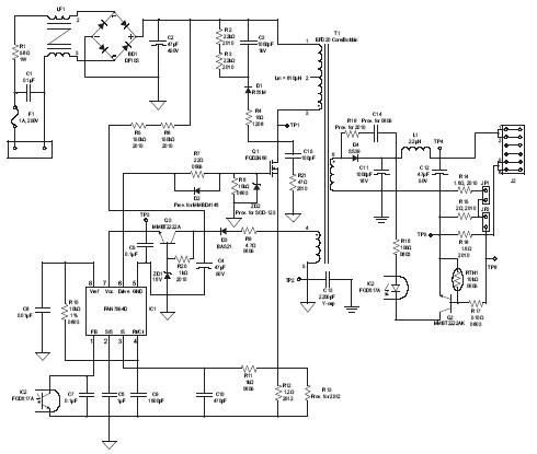
A high brightness LED evaluation board has been developed using the Fairchild Semiconductor FAN7554D PWM controller. The evaluation board for high brightness LEDs incorporates the Fairchild Semiconductor FAN7554D PWM controller, which is designed to provide efficient power management and precise...
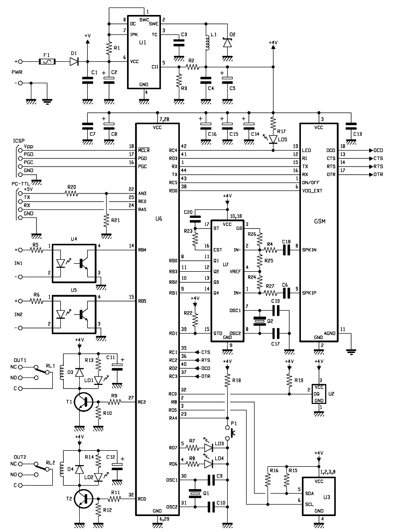
The entire remote control is managed by a PIC that oversees the GSM/GPRS module's operations, monitors room temperature via a Dallas DS1820 smart probe, controls the logical state of two opto-isolated inputs, and sends commands to two relays. Additionally,...