
Wireless keyboard circuit

The described circuit utilizes a common-base configuration for VT3, which is effective in providing high-frequency oscillations. The oscillation frequency is critically determined by the values of capacitors C8 and C9 in conjunction with inductor L1, which forms a resonant tank circuit. This tank circuit is essential for establishing the desired frequency of oscillation, allowing for precise tuning of the circuit's output.
VT2, functioning as a voltage amplification stage, plays a crucial role in enhancing the amplitude of the audio signal before it is fed back into the circuit. This feedback mechanism is vital for maintaining the oscillation and ensuring the stability of the output signal. The modulation of the high-frequency signal by the audio input is achieved through the interaction with L2, which serves as a coupling inductor, facilitating the transfer of energy and information between the high-frequency oscillator and the audio signal path.
The overall design of this circuit is particularly suited for applications requiring amplitude modulation of audio signals, such as in communication systems or audio processing equipment. The careful selection of component values and the configuration of the circuit elements are paramount for achieving optimal performance, including desired frequency response and signal integrity.Circuit works:, VT3 and peripheral components configured as a common-base capacitance feedback oscillation circuit, the oscillation frequency is determined by C8, C9, L1. VT2 voltage amplification stage, and put back the audio signal with a large amplitude to the high frequency signal VT3 is amplitude modulated with high frequency signal emitted by the L2.
Related Circuits
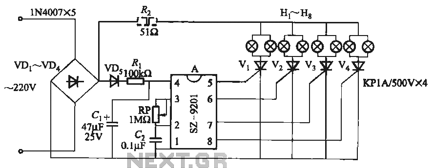
It utilizes the mains supply through a basic DC rectifier circuit. The circuit operates by converting alternating current (AC) from the mains supply into direct current (DC) using a rectifier. A typical implementation involves a bridge rectifier configuration, which consists...

This portable FM transmitter features a limiter, a microphone amplifier, and PLL digital tuning, all integrated onto a single circuit board. The RF power output can be switched between 1 W (high) and 0.2 W (low). The schematic is...
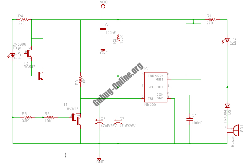
This design circuit project involves a clear glass sensor circuit intended for experimental or hobbyist applications. The concept is straightforward and relies on a homemade sensor unit that includes one high-efficiency ultra-bright red LED (D1) and a standard phototransistor. The...
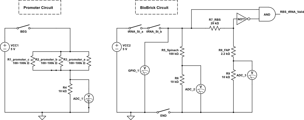
The kit employs an off-the-shelf microcontroller based on the AtMega328P-PU Arduino, along with a simplified version designed for ease of replication and modification by collaborators and students. This initiative aims to enable the fabrication of simplified microcontrollers for DIY...

This ultrasonic sensor circuit consists of a set of ultrasonic receivers and transmitters that operate at the same frequency. When an object moves within the covered area, the circuit's balance is disturbed, triggering the alarm. The ultrasonic circuit is...
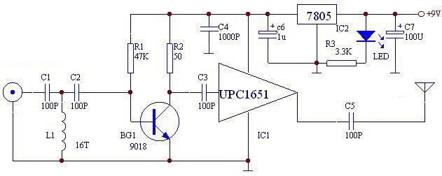
The UPC1651 FM monolithic circuit can be utilized to design a simple, low-cost FM transmitter electronic project. This circuit is specifically designed as a wideband amplifier that covers the HF band through the UHF band. Audio signals from the...