
Speech Filter

is added to form a narrow bandpass around 800 Hz. To use this. the CW Morse beat note is adjusted to the bandpass centre frequency. In the following paragraphs operation of the circuit is described. If filter terminology used appears unfamiliar, the reader is referred to the opening paragraphs of the writer`s previous article (reference 1). The article also discusses a little more about the types of filter employed here. The circuit makes use of the National Semiconductor switched capacitor LP filter package type MF6. which includes two operational amplifiers with the sixth order Butterworth filter. The filter is also operated from its own internal clock operating at 50 times the cut-off frequency. To achieve the 2. 5 kHz and 800 Hz LP cut-off, the clock frequency is switched between 125 kHz and 40 kHz respectively.
As a sixth order Butterworth, the switched capacitor filter has an attenuation slope beyond cut-off of 36 dB per octave. To produce the 800 Hz high pass, one of the operational amplifiers is connected as a second order Chebychev filter.
This type filter gives a theoretical attenuation at the first octave of 17 dB, not as great as the LP filter but quite effective in reducing audio noise or interference below the 800 Hz centre frequency. Figure 1 illustrates the filter system in block form. For speech, the LP filter is operated on its own. For CW its cut-off frequency is lowered and its output fed via the HP filter section. Switched capacitor filters produce spurious output signals if fed with a frequency close to their clock frequency.
To guard against any such signal coming from the receiver, the switched capacitor filter is fed via a simple anti-alias filter with a roll-off above 5 kHz. For circuit detail, refer to Figure 2. The MF6 package operates on a split power rail basis and a centre rail is derived from the single DC supply with resistors R11 and R12.
Supply voltage is not critical and the circuit works on any well-filtered single DC supply between 8 and 14 volts. The clock frequency is set by components C3, R4 and R5. Switch S1 selects speech or CW and its contacts S1a alter the resistance in the circuit to change the clock frequency and hence the LP cut-off frequency.
Components C8, C9, R7, R8, R9 and R10 make up the HP Chebychev active filter in conjunction with one of the MF6 internal operational amplifiers. Switch contacts S1b connect the output either direct from the LP circuit or via the HP circuit. The non-inverting input of the second operational amplifier is connected internally to centre rail, so this amplifier has had to be used in the inverting mode.
Roll-over above 5 kHz for the anti-alias filter is partly done by capacitor C4 in the amplifier feedback circuit and partly by capacitor C1 at the input. If required, the filter can be used as a stand-alone unit with its input fed from the output of a receiver or transceiver headphones jack.
The output of the filter is suitable to operate into high impedance headphones. To operate a loudspeaker, a power amplifier such as the LM380 or LM386 can be added. Of course, the load current of these power amplifiers swings widely with variation in audio level and they require a well regulated power source, preferably isolated from the filter supply. One characteristic of the switched capacitor filter is that there are output components near clock frequency.
With the lowest cut-off at 800 Hz, these components are no lower in frequency than around 40 kHz and could easily be electrically filtered out. However, as they are outside the frequency range of t 🔗 External reference
Related Circuits
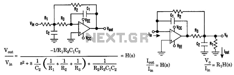
The low-pass Sallen-Key filter is a staple for designers because it contains few components. By redesigning the filter, a current-to-voltage conversion can be avoided when the input signal to be filtered is in current form. The Sallen-Key filter is a...
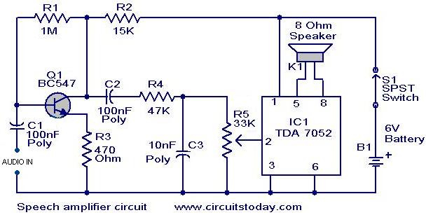
This circuit can be housed within a box containing a speaker to create a convenient microphone amplifier. It is suitable for use by teachers, guides, lecturers, and others in crowded or noisy environments. The design is based on the...
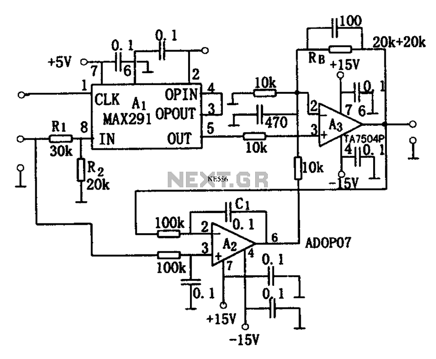
The circuit depicted in Figure 8 is a low-pass filter utilizing an eight-stage switched-capacitor configuration. The cutoff frequency of the circuit can be adjusted, with a clock frequency that can be modified to 1/100 of the original frequency. A...
By using transformers, both voltage feedback and current feedback can be applied. An article by DJ2LR Ulrich Rohde in Ham Radio, November 1979, provides details about this circuit. For the 2.5 MHz to audio converter, the transformation ratio from...
The acoustic filters are met in various points in the sound systems. The knownest application they are the filters baxandal for regulating tone low and high frequencies and filters crossover where the acoustic region is separated in subareas, in...
On this page three adjustable notch filters configurations are shown. They can be used in your small pre-amp or amplifier project to filter out any HUM at 50 Hz (European) or 60Hz. By substituting the capacitors values in the...