
low pass filter subwoofer

The acoustic filter circuit described is designed to manage frequency ranges within sound systems, specifically focusing on limiting the acoustic region from 20 Hz to 100 Hz. This is particularly useful in applications requiring bass management, such as subwoofers or low-frequency sound reinforcement. The circuit employs a bandpass filter configuration, which is essential for isolating the desired frequency range while attenuating frequencies outside this range.
The circuit utilizes operational amplifiers (op-amps) of the dual type, such as the TL082 or NE5532, which are known for their low noise and high performance. These op-amps are configured in a way that allows for active filtering, providing better control over the frequency response compared to passive components alone. The filter design likely incorporates feedback loops to enhance stability and ensure that the desired frequency characteristics are maintained.
Power supply requirements for the circuit are specified as ±12V, which is a common voltage level for op-amp circuits, enabling sufficient headroom for signal processing without distortion. The design may include additional components such as resistors and capacitors that define the cutoff frequencies and shape the filter response. The implementation of such a filter is critical for optimizing the performance of loudspeakers by ensuring that they only receive the frequencies they are designed to reproduce effectively, thereby improving overall sound quality and system efficiency.
In summary, this acoustic filter circuit presents a practical solution for managing low-frequency audio signals, utilizing reliable operational amplifiers and a well-defined frequency response to achieve the desired acoustic performance in sound systems.The acoustic filters are met in various points in the sound systems. The knownest application they are the filters baxandal for regulating tone low and high frequencies and filters crossover where the acoustic region is separated in subareas, in order to it leads the corresponding loudspeakers. The application that to you we propose is a simple filter of region that limits the acoustic region (20-20000Hz) in the region 20-100Hz.
The manufacture end needs a circuit of catering with operational tendency of catering equal with ±12. the operational amplifiers that constitute the active elements for this circuits of are double operational type as the TL082 and NE5532.
The operation 🔗 External reference
Related Circuits
The subwoofer is a speaker designed to reproduce low frequencies, specifically in the range of 20 Hz to 150 Hz. The electronic circuit diagram below illustrates the details of a subwoofer amplifier using the TDA1516, a 22-watt amplifier suitable...
This design was developed by request of a correspondent having made a sort of LED candle and needing to switch off the LED with a puff. This simple, easy to build gadget can be useful as a prop for...
The automotive electronic code lock circuit is depicted above. IC1 is a dedicated lock for the integrated circuit 5G058, with its designated pins connecting an external key switch to the power supply. There are six valid input keys, and...
The all-analog circuit presented controls the rate at which a miniature turbojet engine can be throttled. Increasing or decreasing the throttle too quickly on a miniature turbojet engine, or any jet engine, can lead to quick failure in flight,...
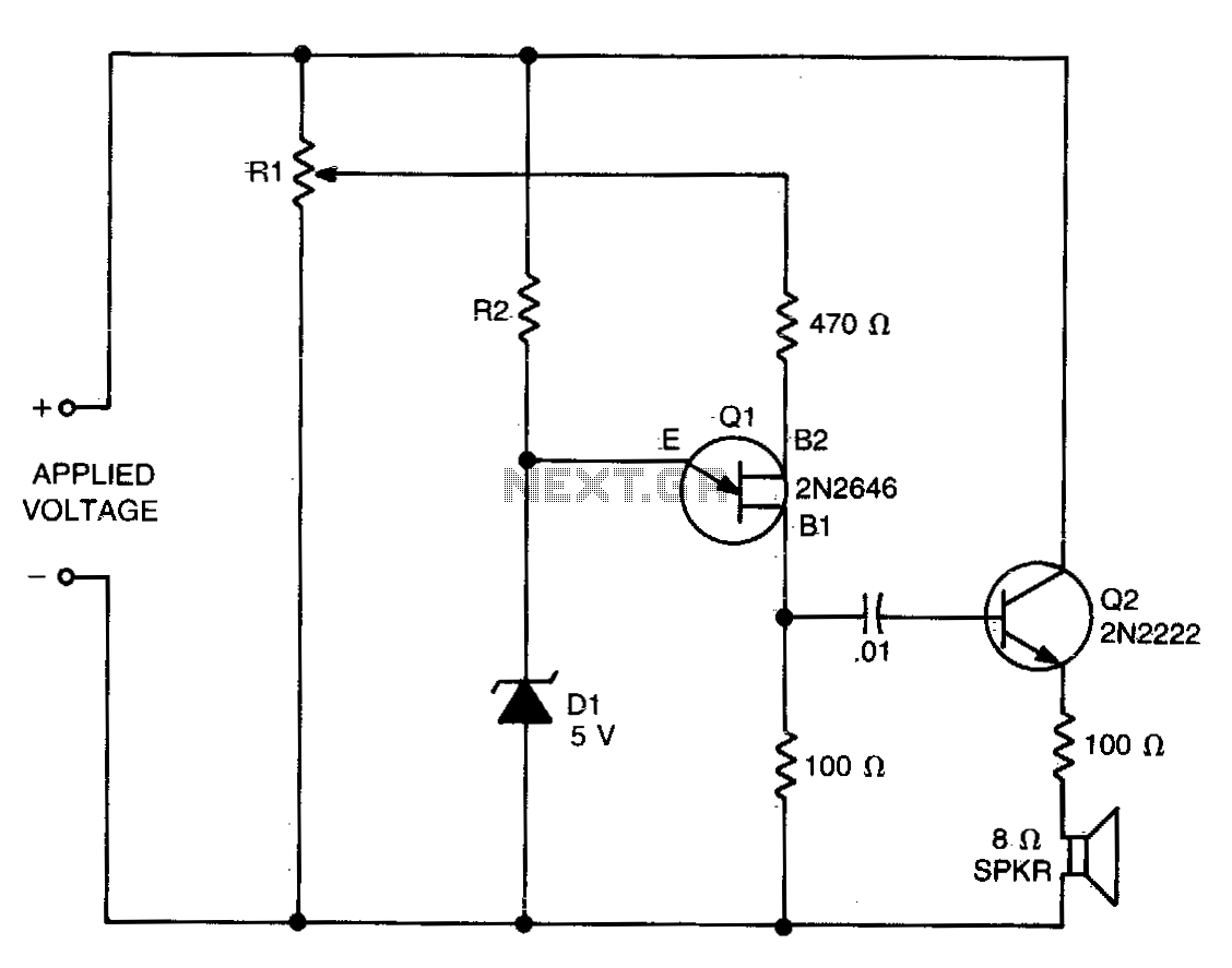
The values of R1, R2, and D1 are selected based on the voltage applied. Using a 12-volt battery, R1 is set to 10 kΩ, R2 to 5 kΩ, and D1 is a 5-volt zener diode or a string of...
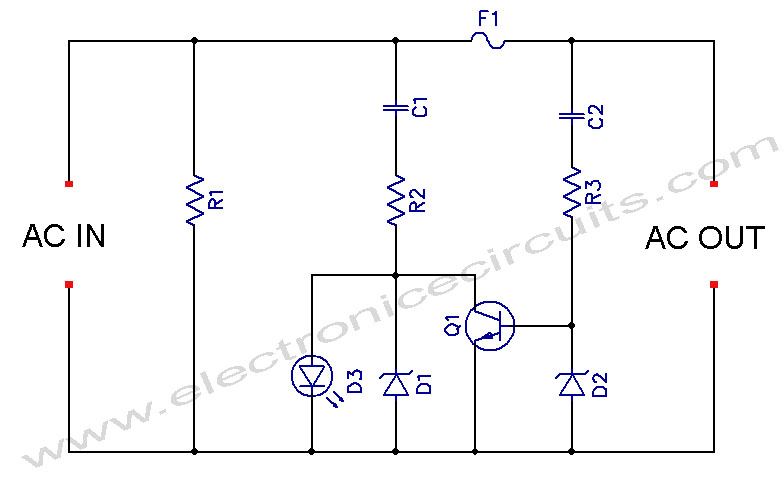
LED Blown AC Fuse Indicator Circuit Diagram. This circuit monitors an AC fuse. In this circuit, the LED indicator shows whether or not the fuse is blown. The LED Blown AC Fuse Indicator Circuit is designed to provide a visual...