
Speech amplifier circuit

The microphone amplifier circuit utilizes the TDA 7052 IC, which is well-suited for audio amplification applications due to its low distortion and high efficiency. The circuit's architecture includes a pre-amplification stage using the BC 547 transistor, which serves to amplify the weak audio signals from the microphone before they reach the main amplifier IC. This pre-amplification is critical in ensuring that the subsequent amplification stage operates effectively, particularly in environments with significant background noise.
The potentiometer (POTR5) allows for user-adjustable volume control, enabling the operator to tailor the output level to suit the specific environment and audience size. This feature is essential for maintaining clarity and preventing audio distortion, especially in dynamic settings where ambient noise levels may fluctuate.
Capacitor C3 plays a pivotal role in maintaining sound quality by filtering out unwanted high-frequency signals that could lead to feedback loops, commonly referred to as the Larsen effect. By bypassing these frequencies, the circuit minimizes the risk of howling and ensures a smoother audio experience for both the speaker and the audience.
Overall, the design of this microphone amplifier circuit is practical and efficient, making it an ideal solution for enhancing audio delivery in various public speaking scenarios. Its compact design allows for easy integration with portable speaker systems, ensuring that users can effectively communicate even in challenging acoustic environments.This circuit given here can be housed in the box containing the speaker to form a handy microphone amplifier. The device can be used by teachers, guides, lecturers etc for speaking in a crowdy or noisy environment.
The circuit is designed base on the audio power amplifier IC TDA 7052. The IC can deliver a maximum power output of 1. 2 W at a 6V supply. T he audio signal from the microphone is pre amplified by the amplifier based on Q1 (BC 547) and give to the input of IC1 (pin 2). The POTR5 acts as a volume control. The capacitor C3 is used to bye pass the upper frequencies in order to avoid the Larsen`s effect(the microphone picking up speaker output to cause howls).
🔗 External reference
Related Circuits
The amplifier feeding the final amplification stage operates with unstabilized voltage. The output stage, utilizing push-pull operation, exhibits significant rejection of the supply voltage. However, the earlier stages do not provide the same level of rejection, resulting in unwanted...
There are two regulator circuits that utilize the L200 integrated circuit from SGS-Thomson to regulate voltage and current. In circuit Fig. 1, the output voltage can be adjusted using the variable resistor RV1. In Fig. 2, both output voltage...
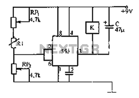
The 555 timer integrates both analog and digital functions within a scaled integrated device. Typically manufactured using a bipolar process, it is designated as the 555 timer, while the CMOS version is referred to as the 7555. In addition...
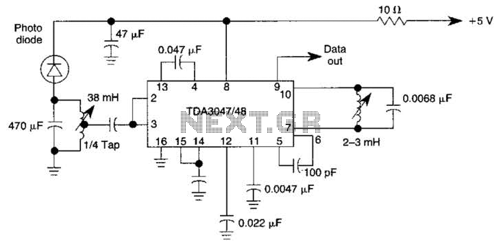
The circuit operates from a 5-V supply and has a current consumption of 2 mA. The output functions as a current source that can drive or suppress a current exceeding 75 mA with a voltage swing of 4.5 V....
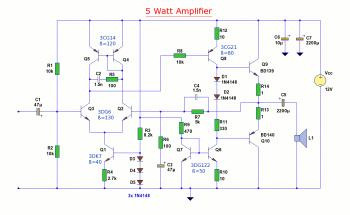
The diagram illustrates a 5W audio amplifier circuit constructed using power transistors BD139 and BD140 for the final amplification stage. This compact amplifier serves as a general-purpose amplifier suitable for applications such as computer audio, radio, MP3 players, and...
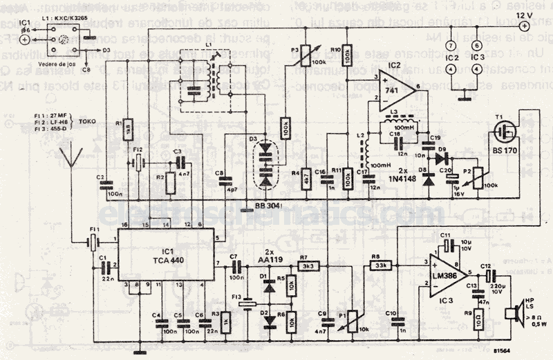
Narrow Band Frequency Modulation (NBFM) is utilized in this 27 MHz transmitter circuit schematic. This circuit is based on the Motorola MC2833 VHF transmitter, which integrates FM modulation and narrow band capabilities into a single chip. P1 is designated...