
speed control of dc motor

The circuit described utilizes an ATMEL89C52 microcontroller to manage the speed of a DC motor through pulse width modulation (PWM). This method allows for efficient control of the motor's speed by adjusting the average voltage supplied to the motor. The microcontroller generates a PWM signal, which is fed into a transistor acting as a switch. The transistor is configured to operate in saturation and cutoff regions, enabling it to turn on and off rapidly.
An optocoupler is employed in this circuit to provide feedback from the motor. The optocoupler isolates the microcontroller from the motor circuit, ensuring that any voltage spikes or noise generated by the motor do not affect the microcontroller's operation. The feedback signal from the optocoupler allows the microcontroller to monitor the actual speed of the motor, facilitating closed-loop control.
By varying the duty cycle of the PWM signal, the average voltage applied to the motor can be adjusted, thereby controlling its speed. A higher duty cycle results in more power delivered to the motor, increasing its speed, while a lower duty cycle decreases the power and slows the motor down. This method is efficient and allows for precise control of motor speed.
The schematic diagram associated with this circuit illustrates the connections between the microcontroller, transistor, optocoupler, and the DC motor. It is essential to ensure that the components are rated appropriately for the motor's voltage and current requirements to prevent damage. Additionally, proper heat sinking should be considered for the transistor if high currents are involved.speed of the d.c. motor is controlled by using ATMEL89C52 lmicrocontroller ,feedback from optocoupler. the circuit diagram can be seen above(click on the diagram to get larger view) the motor speed is controlled by the use of transistor as control switch varying the dutycycle of the switching signal to the transistor varies the power of.. 🔗 External reference
Related Circuits
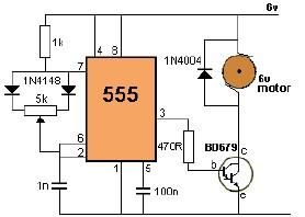
This project utilizes a 555 timer to control the speed of a 6-volt DC motor. Speed adjustment is achieved by rotating a 50 kΩ potentiometer either to the left or right. The circuit employs a 555 timer configured in astable...
This simple circuit and program listing allows the Maximite microcomputer (SILICON CHIP, March-May 2011) to control a stepper motor. It can be expanded to control multiple motors, using four of the Maximite's external I/O pins for each motor with...
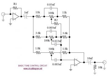
The following diagram illustrates the schematic of an Active Tone Control circuit, commonly referred to as "ACTOR." The ACTOR is an electronic audio circuit designed to enhance loudness by adjusting bass and treble audio signals. It operates using the...
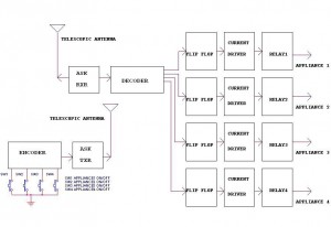
This circuit illustrates a remote control circuit diagram using RF technology without the use of a microcontroller. Features include a simple remote control circuit that operates via radio frequency. The remote control circuit operates by transmitting signals through radio waves,...

This device features a small DC motor fan situated above a container filled with deodorant liquid or gel, powered by a D cell battery. A photocell is integrated to deactivate the fan in low light conditions. An LED indicator...
This is a simple servo tester which will comprehensively test the capabilities of almost any modern servo. It has two pushbuttons, CENTRE and SWEEP and a potentiometer which works as follows: CENTRE Does exactly that, centers the servo, afterwards...