
dc motor control using 555 timer circuit

The circuit employs a 555 timer configured in astable mode to generate a pulse-width modulation (PWM) signal. This PWM signal is then used to control the average voltage supplied to the DC motor, thus regulating its speed.
The 555 timer's duty cycle can be adjusted by changing the resistance of the potentiometer, which in turn alters the width of the pulses generated. The motor is powered by a 6-volt supply, and the output from the 555 timer is fed into a transistor that acts as a switch. The transistor amplifies the PWM signal, allowing it to drive the motor effectively.
Key components of the circuit include the 555 timer IC, a 50 kΩ potentiometer, a suitable NPN transistor (such as the 2N2222), a diode for flyback protection, and the 6-volt DC motor. The diode is connected in reverse parallel with the motor to protect the circuit from voltage spikes generated when the motor is turned off.
The schematic representation of this circuit should include the connections between the 555 timer, the potentiometer, the transistor, the motor, and the power supply, ensuring that all components are properly oriented and connected to allow smooth operation. This design provides a straightforward method for controlling DC motor speed in various applications.Using this 555 timer DC motor control electronic project you can control speed of a 6 volts DC motor, by simply rotate left or right the 50 k potentiometer. 🔗 External reference
Related Circuits
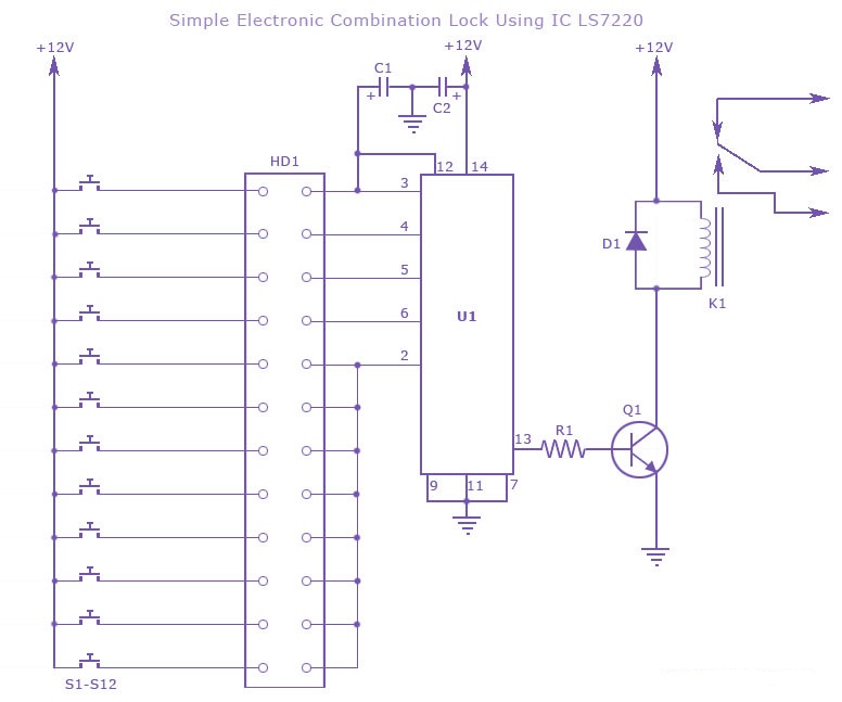
A simple electronic combination lock using the IC LS7220. This circuit employs a relay to control any device when a combination of four digits is entered. Keypads serve as the input method for entering the digits, and the correct...
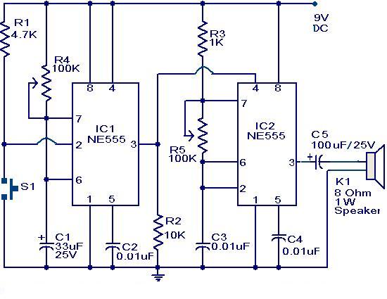
The primary component of this circuit is a doorbell utilizing two NE555 timer ICs. When the switch S1 is momentarily pressed, the speaker produces a bell sound, which is determined by the time period of the monostable multivibrator configured...
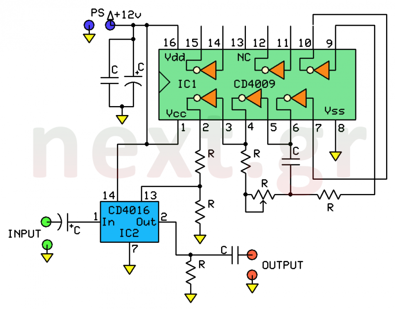
This system is a straightforward and dependable mechanism for processing human speech. Its primary function is to modify the tone of the human voice, making it sound artificial, similar to a robotic voice produced through artificial means. This circuit...
The primary objective is to present the circuit diagram and describe the software utilized. A UDP application is employed to transmit commands to the microcontroller, which subsequently activates or deactivates the relay. It is anticipated that TCP implementation could...
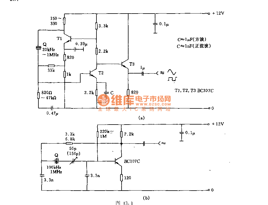
Figures (a) and (b) illustrate two basic oscillator circuits operating at 2 MHz. The circuit design allows for adjustment of the optimal operating point through testing. The two oscillator circuits depicted in the figures utilize different configurations to achieve stable...
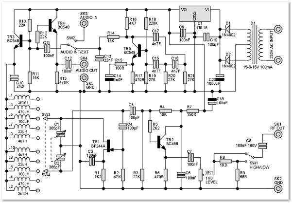
This signal generator is designed for the realignment of radio receivers. The unit is inexpensive and relatively simple but adequately serves its intended purpose. However, the output is not a pure sine wave, which may make it unsuitable for...