
Speed-limit Alert

The speed-limit alert system is designed to monitor the speed of internal combustion engine vehicles and provide a wireless alert when a set speed limit is exceeded. The circuit incorporates various resistors to create a voltage divider and set thresholds for the alert system.
The resistors R1, R2, and R19, each rated at 1K ohms and 1/4 watt, are used for biasing and setting the reference voltage for the operational amplifiers in the circuit. Resistors R3 through R6, R13, and R17, all rated at 100K ohms and 1/4 watt, are likely used in the feedback network of the operational amplifiers, determining the gain and response time of the alert system.
Resistors R7 and R15, rated at 1M ohm and 1/4 watt, play a critical role in the input stage of the circuit, ensuring that the signal from the vehicle's speed sensor is adequately amplified for processing. The inclusion of R8, a 50K ohm variable trimmer resistor rated at 1/2 watt, allows for fine-tuning of the circuit, enabling the user to adjust the sensitivity of the speed detection mechanism.
Finally, R9, a 470 ohm resistor, is likely used in conjunction with other components to limit current and protect sensitive parts of the circuit from excessive voltage levels. This combination of components allows for a robust design that can adapt to various vehicle types while maintaining reliable performance in alerting the driver when speed limits are exceeded.
In conclusion, this speed-limit alert system is an essential tool for enhancing road safety and promoting adherence to traffic regulations in vehicles equipped with internal combustion engines. Its wireless capabilities ensure ease of installation and operation, making it a practical solution for modern vehicles.Speed-limit Alert Wireless portable unit Adaptable with most internal combustion engine vehicles Circuit diagram Parts: R1,R2,R19 1K 1/4W Resistors R3-R6,R13,R17 100K 1/4W Resistors R7,R15 1M 1/4W Resistors R8 50K 1/2W Trimmer Cermet R9 470.. 🔗 External reference
Related Circuits
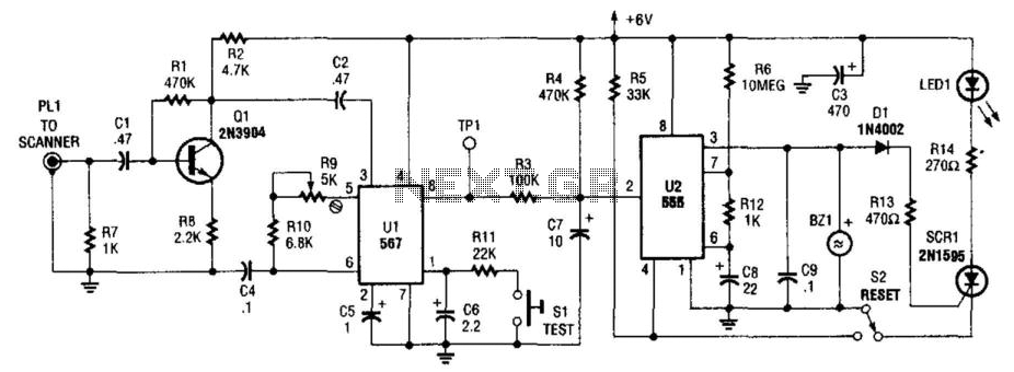
This circuit detects the 1050-Hz tone transmitted by NOAA (National Oceanic and Atmospheric Administration) weather radio stations, which operate within the frequency range of 162.40 to 162.55 MHz. The tone is emitted for several seconds. Q1 functions as an...
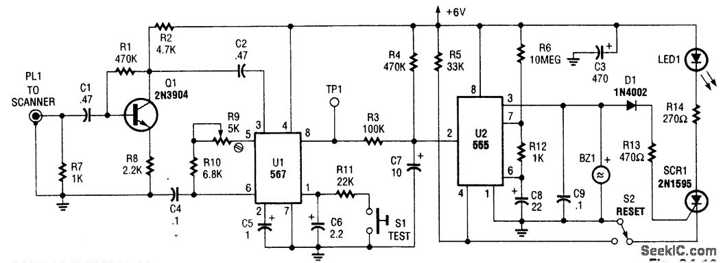
This circuit detects the 1050 Hz tone transmitted by NOAA (National Oceanic and Atmospheric Administration) Weather radio stations that operate within the frequency range of 162.40 to 162.55 MHz. The tone lasts for several seconds. Q1 serves as an...
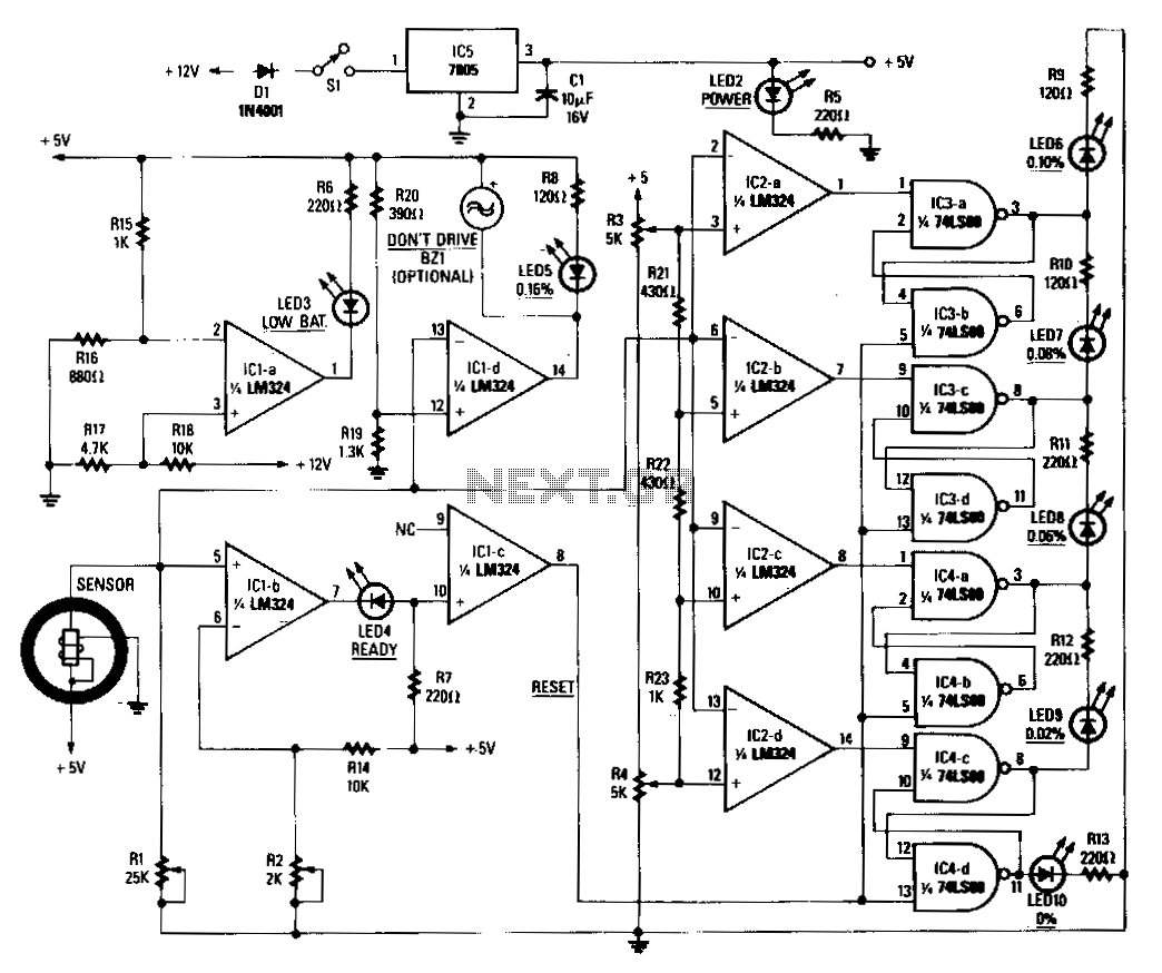
When power is applied to the circuit, the heater coil in the sensor is energized by the 5-V output of IC5, a 7805 voltage regulator. Breathing into the sensor with alcohol on one's breath will lower the sensor's resistance;...
The following circuit illustrates a Mains Remote-Alert Circuit Diagram. Features include simple circuitry, with the transmitted signal being conveyed effectively. The Mains Remote-Alert Circuit is designed to provide a notification system that alerts users about the status of mains power....
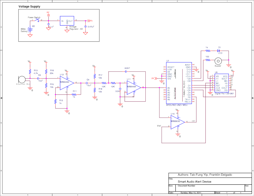
This is a senior project from Stony Brook University, designed and implemented by Tak-Fung Yip and Franklin Delgado, with consultation from Professor Milutin Stanac. The senior project from Stony Brook University represents a collaborative effort in the field of electronics...
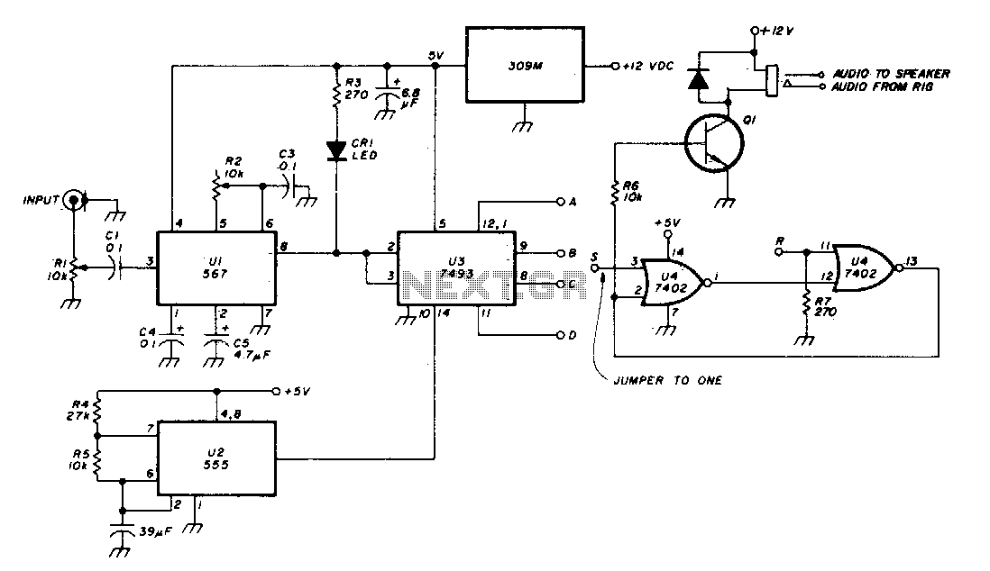
The Phase-Locked Loop (PLL) integrated circuit (U1) is configured with resistor R2 to achieve the desired tone frequency. An LED indicator is used to show when the PLL has locked onto the signal. To ensure proper lock-up, the signal...