
Speed regulator for dc motors

The described circuit employs a four thyristor controlled bridge configuration, which is adept at managing bidirectional power flow and is suitable for applications requiring control in both forward and reverse directions of torque. This capability is crucial in various industrial motor control applications, allowing for efficient operation in two quadrants of the torque-speed curve, specifically the motoring and regenerative braking modes.
The innovative use of self-biased circuits in the trigger section replaces traditional pulse transformers, thereby minimizing the power drawn from the gate and enhancing the overall efficiency of the system. This design choice not only reduces power consumption but also improves noise immunity, which is vital in environments where electromagnetic interference could affect performance.
The incorporation of optocouplers provides electrical isolation between the control side and the power side of the circuit, ensuring that high voltages do not affect the sensitive control circuitry. This isolation is critical for maintaining the integrity and safety of the control signals, particularly in high-power applications.
Trigger pulses are generated through a comparison mechanism that involves an error signal derived from the difference between the actual speed of the motor and a reference speed signal. This error signal is first amplified and processed to ensure that it is suitable for triggering the thyristors. The line synchronism signal serves as a timing reference, enabling precise control of the thyristors in relation to the AC supply, which is essential for maintaining the desired output characteristics.
The output of the converter is a DC voltage that is directly proportional to the motor speed, facilitating smooth and efficient control over the motor's operation. By continuously comparing this output with a reference signal, the system can dynamically adjust the firing angles of the thyristors, thereby regulating the speed and torque as required by the application. This feedback mechanism ensures that the motor operates optimally under varying load conditions, enhancing performance and reliability.A four thyristor controlled bridge is used for operation in two quadrants of the torque-speed characteristics. In the trigger circuits the usual pulse transformers were replaced by self biased circuits which minimize gate power consumption and increase noise immunity.
Electrical isolation is guaranteed by the use of optocouplers. The trigger pulses are generated by the comparison between an error signal, previously processed and amplified, and a line synchronism signal. The converter's output is a dc voltage proportional to the speed, which after being compared with a reference signal, becomes the error signal.
Related Circuits
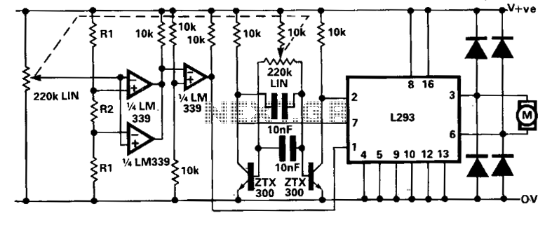
A limitation of the bi-directional proportional motor control circuit is that when the potentiometer is in its center position, the motor does not stop but continues to creep. This occurs due to the challenge of precisely adjusting the potentiometer...
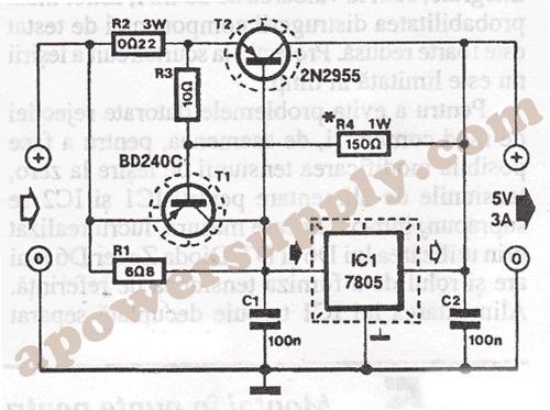
Voltage regulator ICs with 3 pins, from the LM7805 and LM7812 series, are excellent for use in voltage regulator circuits. If higher currents are required, up to... Voltage regulator integrated circuits (ICs), specifically from the LM7805 and LM7812 series, serve...
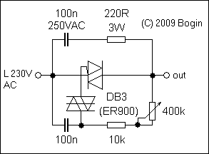
This circuit, commonly referred to as the poor man's variac, is utilized in various applications across consumer and industrial electronics where a perfectly sinusoidal waveform is not necessary, and a traditional variac (variable autotransformer) would be excessively heavy and...
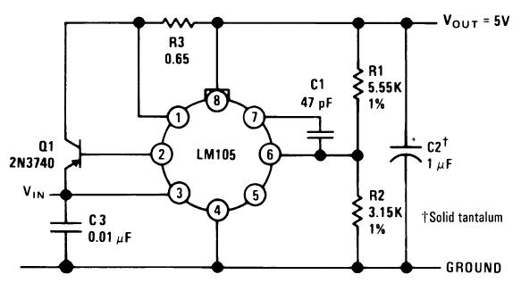
A single diffused, wide base transistor, such as the 2N3740, is recommended due to its reduced tendency to cause oscillation issues compared to double diffused, planar devices. Additionally, it exhibits greater reliability under overload conditions, and low-cost options are...
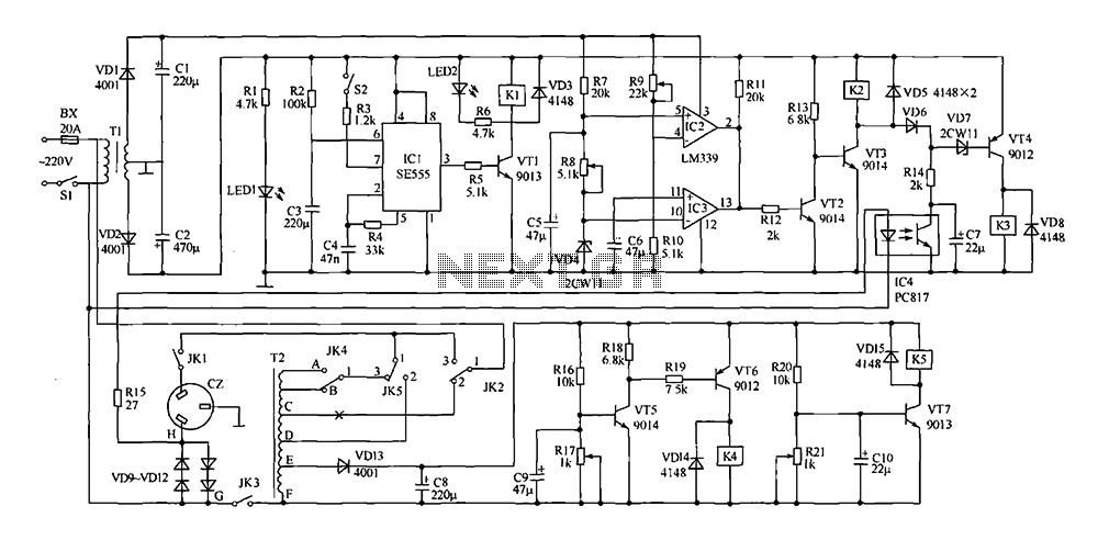
This document presents a power-saving voltage regulator circuit. In addition to its general function as a delay regulator, the circuit features: (1) an automatic voltage regulation capability for mains voltage within a range of 220V ±10%, allowing direct power...
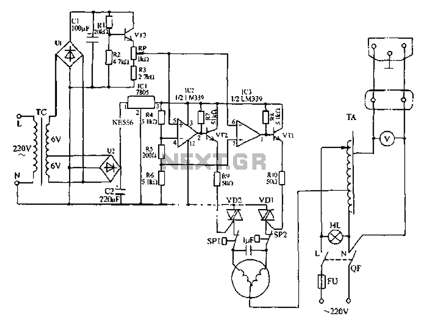
Automatic AC voltage regulator circuit The automatic AC voltage regulator circuit is designed to maintain a stable output voltage despite fluctuations in the input voltage. This circuit is essential for protecting sensitive electronic devices from voltage variations that can lead...