
Motor speed control circuit

The modified bi-directional proportional motor control circuit addresses the inherent limitation of continuous motor movement when the potentiometer is centered. The original circuit's reliance on a single potentiometer made it difficult to achieve a precise 1:1 mark-space ratio, leading to undesired motor creep.
In this enhanced design, a second potentiometer is employed, effectively ganged with the first. This configuration allows for better control over the motor's behavior by providing an additional adjustment mechanism. The second potentiometer is strategically connected between the power supply lines, enabling it to create a voltage reference that can be monitored by a window comparator.
The window comparator serves a critical role in this circuit modification. It compares the voltage levels from the second potentiometer against predefined thresholds. When the voltage from the second potentiometer falls within a specific range, the window comparator activates the inhibit input of the L293 motor driver. This action effectively cuts off the drive signal to the motor, preventing it from creeping when the primary potentiometer is near its center position.
The L293 motor driver is a dual H-bridge driver that allows for bi-directional control of DC motors. By integrating the window comparator with the L293, the circuit achieves a more stable and responsive motor control system. The combination of these components ensures that the motor can be accurately stopped when the potentiometer is adjusted to the center position, enhancing the overall functionality and performance of the motor control circuit.
In summary, this modified circuit design significantly improves the usability of the bi-directional proportional motor control system by incorporating an additional potentiometer and a window comparator, effectively addressing the creeping issue and ensuring precise motor control.A shortcoming of the above bi-directional proportional motor control circuit is that with the potentiometer in its center position the motor does not stop, but creeps due to the difficulty in setting the potentiometer for an exact 1:1 mark-space ratio from the flip-flop. This modified circuit uses a second potentiometer, ganged with the first used to inhibit drive to the motor near the center position.
This potentiometer is connected between the supply lines and feeds a window comparator which in turn drives the inhibit input of the L293.
Related Circuits
The LM2002 / 2002A is an audio power amplifier integrated circuit. The LM2002A features high voltage protection, with a maximum instantaneous power supply voltage of up to 40V, and comes in a 5-pin single in-line plastic package. This integrated...
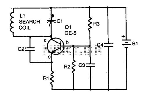
The locator utilizes a transistor radio as the detector. By tuning the radio to a weak station, the capacitor C1 can be adjusted so that the locator's oscillator beats against the received signal. When the search head passes over...
There are monitors that feature only three BNC inputs and utilize composite synchronization (sync on green). This circuit has been specifically designed for such monitors. The design maintains simplicity while delivering reasonable performance. The operational principle is straightforward. The...
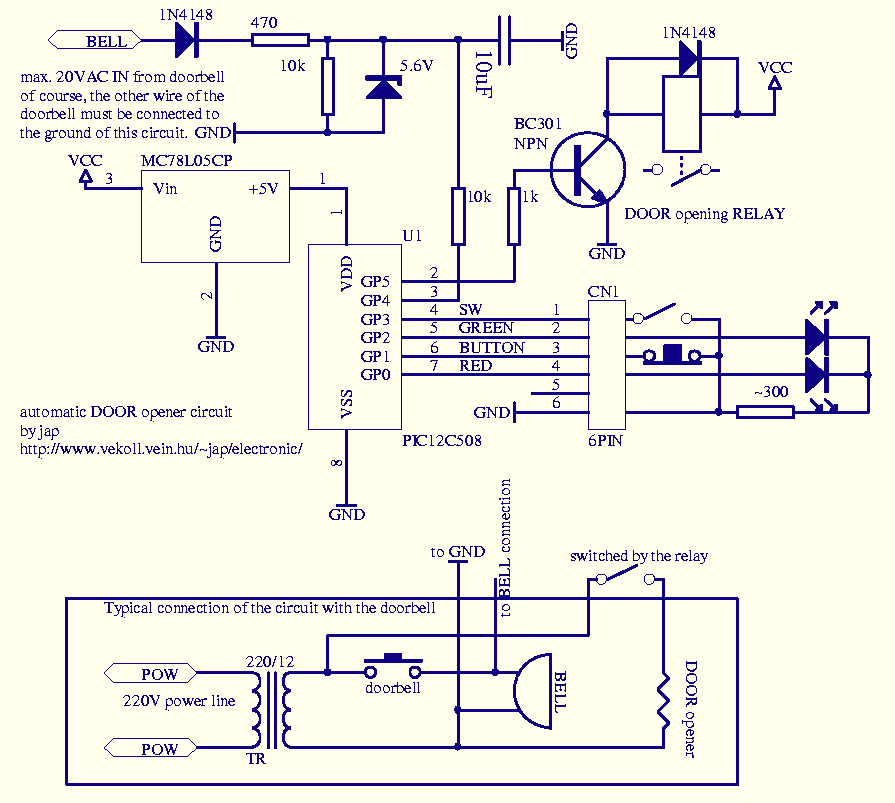
This circuit can be used to operate an electric strike or an electromagnetic lock on a door. It is not the door being opened/closed, but a small electromagnetic strike which unlocks the door. The opener has the following features...
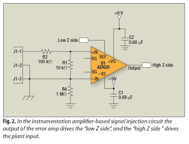
A signal-injection circuit for control-loop analysis is flat from DC to 200 kHz, isolated from chassis ground, and easily constructed with a readily available instrumentation amplifier. The signal-injection circuit is designed to facilitate control-loop analysis by providing a stable and...

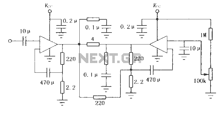
This design circuit is a tone control circuit that utilizes the popular Baxandall configuration, a straightforward circuit layout that allows for continuous boost and cut control. The circuit is inexpensive to construct and is frequently implemented in commercial products....