
Spy Circuit

The circuit in question likely serves a specific function that resonates with a wide audience, contributing to its viral status. It may incorporate innovative features or address common problems faced by users, which can lead to widespread sharing and discussion online. The high engagement metrics suggest that this circuit not only attracts attention but also prompts users to interact with it, whether through comments, modifications, or sharing their own experiences.
To ensure a comprehensive understanding, it is essential to examine the specific components and design of the circuit. This may include a schematic diagram detailing the arrangement of resistors, capacitors, microcontrollers, or other electronic components. The functionality of the circuit should be clearly defined, outlining its purpose, such as signal processing, data transmission, or user interaction.
Additionally, it would be beneficial to explore the potential applications of this circuit in various fields, including consumer electronics, automation, or educational projects. By analyzing the circuit's performance metrics and user feedback, further enhancements could be suggested to improve its reliability and user experience.
In conclusion, the popularity of this circuit highlights the importance of user engagement and community involvement in the development and dissemination of electronic designs.This circuit has to be one that breaks all the internet records. According to the counter on the website above - Top Right (arroncake) - as of May 3, 2013 - it has received 760, 191 views with 412 comments, and today alone - 116 Views. It appears that an entire forum has been built around this circuit. I had to add it here. - John 🔗 External reference
Related Circuits
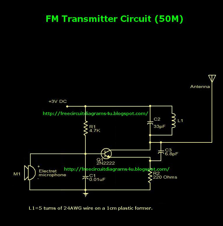
This is an FM transmitter circuit diagram. This circuit uses a 2N2222 transistor, allowing it to operate at 3V and transmit signals up to 50 meters. The FM transmitter circuit consists of several key components, primarily centered around the 2N2222...
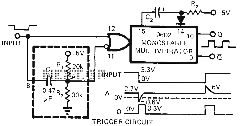
The 9602 multivibrator circuit can trigger either the rising edge or the falling edge of a square wave, but not both simultaneously. To enable double-edge triggering, two additional resistors and a capacitor can be employed. When the input signal...
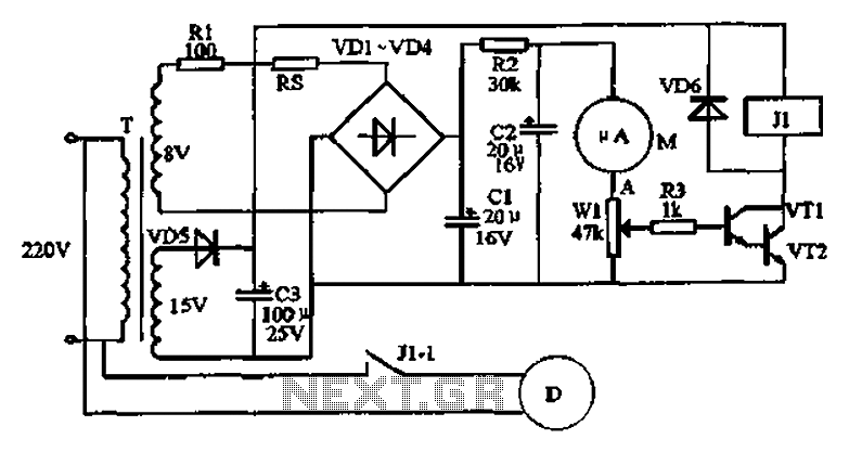
An automatic humidifier can be utilized for humidity control in households, hatcheries, poultry farms, or juvenile poultry houses. When the humidity level falls below 50%, the automatic humidifier activates to maintain a specific humidity level that is beneficial for...

This circuit operates effectively across a broad frequency spectrum. XTAL 1 serves as a fundamental-frequency crystal. Tl and CI are adjusted to match the input frequency. This circuit can be utilized as a straightforward shortwave converter for AM radios,...
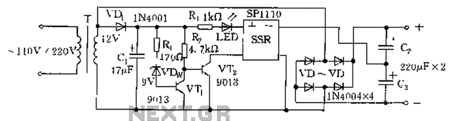
The circuit is automatically converted to a low-voltage configuration. A 220V AC supply is stepped down by transformer T. After this, the breakdown voltage of diode VDw causes transistors VT1 and VT2 to turn off, resulting in the solid-state...
.png)
This document describes a simple engineering project circuit for a mobile cell phone detector (sniffer). This compact mobile communication detector can sense the presence of a mobile device, making it suitable for preventing mobile phone usage in private spaces,...