
Square Wave Oscillator

The circuit employs the LM301 operational amplifier in a configuration designed to produce a square wave output. The operational amplifier's power supply range of 3 V to 36 V provides flexibility for various applications. The maximum operating frequency of 325 kHz makes this design suitable for high-speed switching applications.
The oscillation frequency can be calculated using the formula that incorporates the resistances (R) and capacitance (C) in the circuit, allowing for precise tuning of the output waveform. Capacitor C1 plays a critical role in the timing of the oscillation; it must be adequately rated to handle voltages exceeding two-thirds of the supply voltage to ensure reliable operation.
In this configuration, the inverting input of the LM301 is grounded, maintaining it at zero volts. The non-inverting input is biased to approximately two-thirds of the supply voltage through a voltage divider formed by resistors R1, R2, and R3. This setup establishes a threshold voltage that is essential for the operation of the square wave generator.
As the output of the LM301 transitions, C1 charges and discharges, affecting the voltage at the non-inverting input. When the output voltage exceeds the non-inverting input voltage, the output swings down to zero volts, causing a periodic oscillation that produces the square wave output. The timing and frequency of this oscillation can be adjusted by varying the values of R1, R2, R3, and C1, allowing for a versatile design that can be tailored to specific requirements.
In summary, this circuit design effectively utilizes the LM301 operational amplifier to generate a square wave signal, with careful consideration given to component values and configuration to achieve stable and reliable performance.This scheme applies amplifier OpAmp LM301 to awaken square wave that is simple. LM301 applies power allowance 3 V - 36 V, with highest frequency 325 kHzs. Oscillation frequency given in equation. where f is Hertz, R in Ohm, C in Farad. Active Pressure C1 have to be more a few 2/3 of power allowance tensions. At C1 stands to throw away charge. Input inverting IC LM301 becomes zero volts whereas input non-inverting arrested at tension around 2/3 quantized tensions by R1, R2 and R3. C1 now loaded from output of LM301 through finite R4 of the tension exceeding tension at input non-inverting, that is when output of LM301 sways going down to zero volts.
Input non-inverting LM301 has tension around 1/3 allowance tensions. 🔗 External reference
Related Circuits
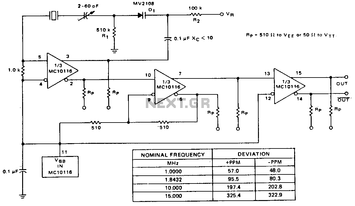
A voltage-variable capacitance tuning diode is connected in series with the crystal feedback path. Adjusting the voltage on the variable resistor (VR) changes the capacitance of the tuning diode, which in turn tunes the oscillator. The 510 kΩ resistor...

At the input of the operational amplifier, a resistor-diode network can be constructed to create a square-law function conversion circuit. This resistor-diode network acts as a voltage divider, where the input voltage variations lead to different partial pressures. The...
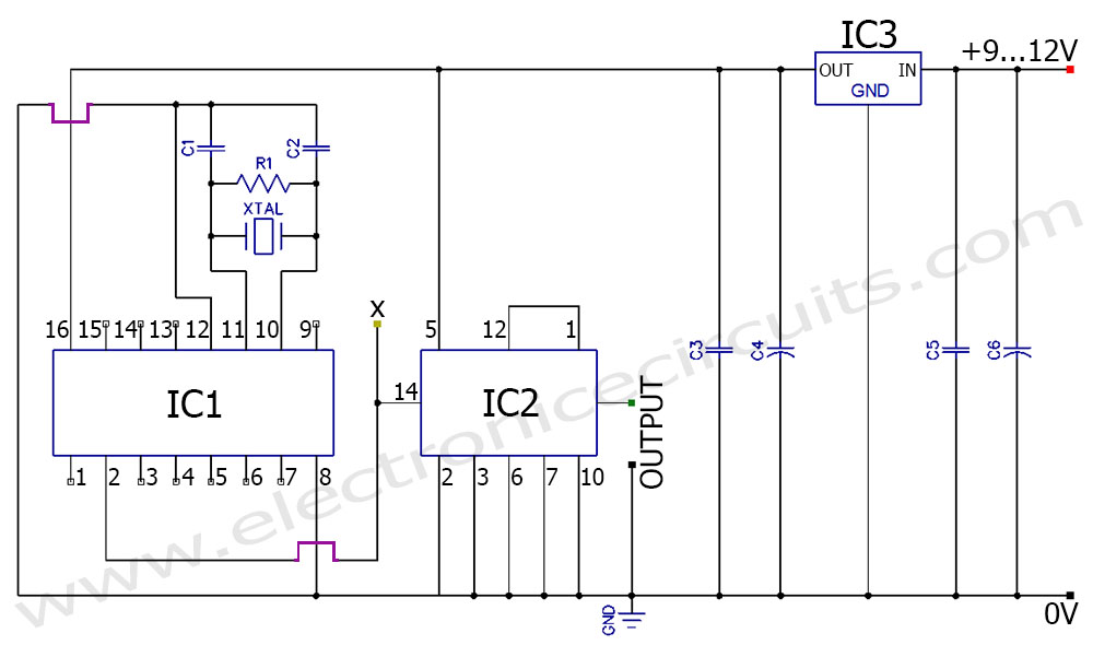
A frequency generator circuit capable of producing 50 Hz and 60 Hz outputs using a crystal oscillator. This oscillator can be utilized to generate precise frequency signals. This frequency generator circuit employs a crystal oscillator as its core component, which...
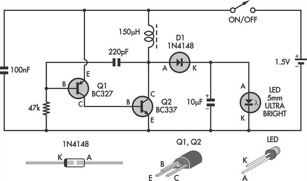
This simple LED torch is driven by a 2-transistor blocking oscillator that steps up the voltage from a 1.5V cell. It relies on the inherent current limiting of the 150 µH choke to protect the white LED from overdrive....
The output frequency can be altered based on the division ratio of the comparison frequency in the 10 kHz unit, with the division ratio set to 1024 in this circuit. Given that the amateur radio bandwidth in Japan is...
The two circuits demonstrate the generation of low-frequency sine waves by shifting the phase of the signal through an RC network, facilitating oscillation when the total phase shift reaches 360 degrees. The transistor circuit on the right produces a...