
Isolated 15 to 1000V DC-DC Converter

The isolated DC-to-DC step-up converter operates by converting a lower input voltage to a higher output voltage while maintaining electrical isolation between the two sides. This is typically achieved using a transformer or an opto-isolator, which serves to separate the input power source from the output load.
In this type of converter, the input voltage is applied to the primary winding of the transformer. As current flows through the primary winding, it generates a magnetic field that induces a voltage in the secondary winding. The output voltage can be adjusted by varying the turns ratio of the transformer, allowing for a range of output voltages based on the input voltage and the desired application.
Key components of an isolated DC-to-DC step-up converter include the transformer, switching elements (such as MOSFETs or IGBTs), diodes, and capacitors. The switching elements are controlled by a pulse-width modulation (PWM) signal, which regulates the duty cycle and, consequently, the output voltage. The diodes are used for rectification, converting the induced AC voltage from the transformer back into DC voltage, while capacitors are employed for smoothing the output voltage and filtering out any ripple.
The benefits of an isolated DC-to-DC step-up converter include improved safety due to the electrical isolation, reduced noise coupling between input and output, and the ability to interface with different ground potentials. These converters are widely used in applications such as battery-powered devices, renewable energy systems, and telecommunications equipment, where voltage levels need to be adjusted efficiently and safely.
Overall, the isolated DC-to-DC step-up converter is a vital component in modern electronic systems, providing versatility and reliability in voltage conversion tasks.The circuit shown in the schematic diagram below is an isolated dc-to-dc step up converter. Being isolated means that there is no electrical connection between.. 🔗 External reference
Related Circuits

The transition from diodes to synchronous-rectification (SR) MOSFETs in the secondary circuits of flyback converters is increasing with each new generation of MOSFETs, enhancing performance with minimal or no cost increase. SR MOSFETs can offer improved efficiency compared to...
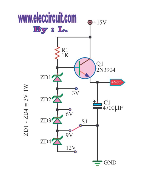
This is a DC regulator circuit that can provide multiple output voltages simply. It functions as a simple step-down DC converter and is designed with a fixed resistor R1. The described circuit operates as a DC voltage regulator, specifically designed...
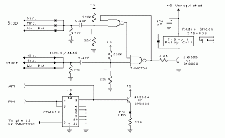
When the power supply is connected to IC1, the output pin 3 operates at a frequency of 1 kHz. The components Q1 and Q2 work in a push-pull configuration. When a positive output signal is generated, Q1 and Q2...
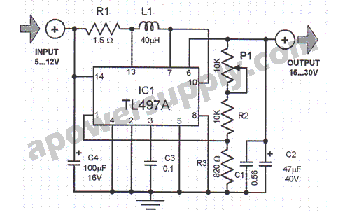
This voltage converter is constructed using the TL497A integrated circuit and is designed to convert an input voltage range of 5 to 12 volts into a higher output voltage range of 15 to 30 volts. This functionality is particularly...
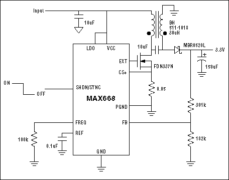
A step-up converter followed by an LDO regulator provides improved battery life compared to a traditional SEPIC design when powered by a single lithium-ion cell. The circuit design features a step-up (boost) converter that elevates the input voltage from a...
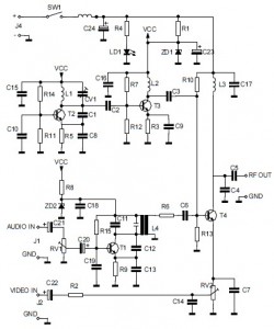
This is the circuit diagram of an audio/video modulator. The circuit converts audio and video signals into a UHF TV signal. It is designed to connect a video signal originating from a camera or other video source to a...