
The Output Adjustable Flyback Converter

The circuit described is a high voltage step-up DC power supply utilizing an adjustable flyback converter topology. This design is particularly effective for applications requiring a significant increase in voltage from a lower voltage DC source. The flyback converter operates by storing energy in the magnetic field of a transformer during the "on" phase and releasing it during the "off" phase, allowing for efficient energy transfer and voltage transformation.
Key components of the flyback converter include a transformer, a switching device (typically a MOSFET), a diode, and output capacitors. The transformer is designed with a primary and secondary winding; the primary winding connects to the input DC voltage source, while the secondary winding is responsible for delivering the stepped-up output voltage.
The switching device is controlled by a pulse-width modulation (PWM) signal, which regulates the duty cycle and, consequently, the output voltage. An adjustable feedback mechanism is often implemented to maintain the desired output voltage, allowing for flexibility in applications. The feedback loop typically involves a voltage divider connected to the output, feeding back into a control circuit that adjusts the PWM signal based on the output voltage level.
The diode in the flyback converter serves as a rectifier, allowing current to flow from the transformer to the output capacitor during the off phase of the switching cycle. The output capacitor smooths the voltage output, reducing ripple and providing a stable DC voltage to the load.
Safety considerations are crucial when designing high voltage power supplies. Proper insulation, component ratings, and circuit protection mechanisms must be implemented to prevent voltage breakdown and ensure reliable operation.
Overall, this high voltage step-up DC power supply using adjustable flyback conversion presents a versatile solution for applications requiring high voltage outputs from lower voltage sources, with the added benefit of adjustable voltage levels for varying requirements.A high voltage step-up DC power supply using adjustable flyback conversion. 🔗 External reference
Related Circuits

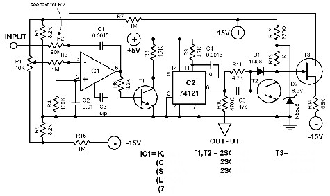
This design outlines a simple wideband output amplifier suitable for use as a 50-ohm transmission line driver. The circuit is constructed using the CA3140 operational amplifier. When utilized alongside the function generator and sine wave shaper circuits, it delivers...
This voltage-to-frequency converter is designed to connect to a frequency counter to display the measured voltage value. This converter-counter combination creates an inexpensive yet functionally complete digital voltmeter. The circuit outputs TTL-compatible pulses that are 5 µs wide. The...
This circuit sequentially lights ten bulbs, first in one direction and then in the opposite direction, creating an appealing visual effect. Gates N1 and N2 form an oscillator, which serves as a clock for the BCD up/down counter CD4510...
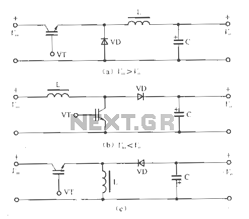
The circuit operates without isolation for both input and output voltage, utilizing a working switch along with an inductor (L), diode (D), and capacitor (C) to form a basic inverter circuit. There are three types of converters: the step-down...
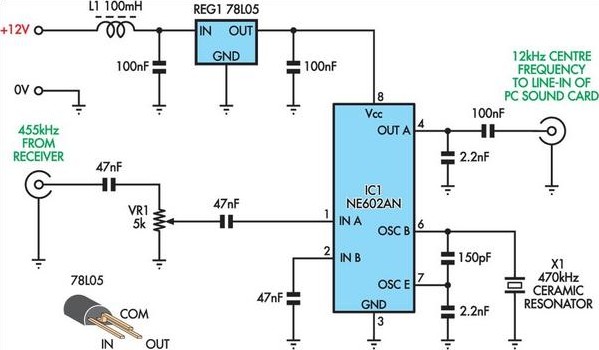
This project originated from an interest in a new form of radio transmission known as Digital Radio Mondial (DRM). The Digital Radio Mondial (DRM) is a revolutionary digital broadcasting technology designed for AM and FM radio. It provides enhanced audio...

Cable and xDSL modems are increasingly popular, leading to a need for designs that interface with existing telephones at subscriber locations. The subscriber line interface circuit (SLIC) within the modem must ring the phone and provide loop current during...