
SR63 holiday lights ASIC

The circuit described operates by first converting an AC voltage of 220V to a DC voltage using a bridge rectifier formed by diodes VD1 to VD4. The output is then utilized to power four lights (H1 to H4) directly, ensuring reliable illumination. Additionally, a secondary pathway involves a buck converter (R1) and a voltage regulator (VD5) to step down the voltage to approximately 5V DC, which is essential for powering low-voltage components within the circuit.
The voltage divider composed of resistors R2 and R3 serves a dual purpose: it not only stabilizes the voltage supply to manifold A but also generates a synchronization signal that is critical for the timing functions of the circuit. The oscillator circuit, which includes RP1, R4, C3, and SR63, is designed to produce a variable frequency output. By adjusting RP1, the frequency of oscillation can be modified, which in turn influences the chase speed of the lights, allowing for dynamic visual effects.
Furthermore, RP2 is integrated into the dimming oscillator circuit, providing the capability to adjust the brightness of the lights. The adjustment of RP2 affects both the speed and the contrast of the light output, enabling a range of visual presentations from bright to dim settings.
The control terminals for the four lights can be connected to a switch or configured for a specific operation mode, as indicated in the referenced table 2-41. This flexibility allows for the customization of the lighting effects based on user requirements or specific application scenarios, making this circuit suitable for various lighting control applications.220V AC after VDI ~ VD4 bridge rectifier, the output of a point, all the way to direct electricity for lights H1 ~ H4; another way through Rl buck, VD5 regulator, about 5v DC o utput voltage, the electricity supply manifold A. R2, R3 form a voltage divider provides a synchronization signal for the manifold A. RP1, R4, C3 and SR63 within the oscillator circuit system, adjust the value of the RPI system can change the oscillation frequency rate, muscle and can be adjusted four lights chase speed. RP2 inner circuit dimming oscillator circuit, the adjustment value of RP2 can change the speed and dimming lights bright and dark contrast.
FIG DIM, Sl, so, TIP missed four control terminal t in the actual production should be connected with a switch or a switching operation according to the pattern need to refer to table 2-41.
Related Circuits
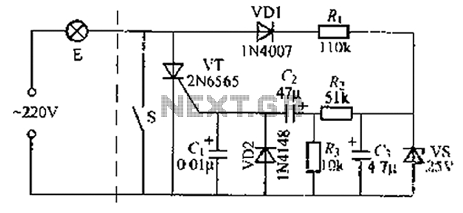
A delay circuit using an improved quenching lamp pull switch is described, focusing on its performance and the delay function in lighting control. The circuit exhibits a high degree of stability and reliability. When switch S is closed, the...
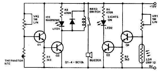
This electronic project circuit diagram for an ice warning and lights reminder system alerts drivers when their vehicle lights should be activated and warns them if the outside temperature approaches zero degrees Celsius. The system employs an LED indicator...
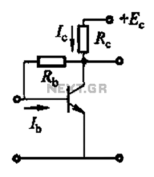
Basic reference bias circuit using a transistor with negative voltage feedback. The basic reference bias circuit utilizing a transistor with negative voltage feedback is designed to provide a stable output voltage or current that is largely independent of variations in...
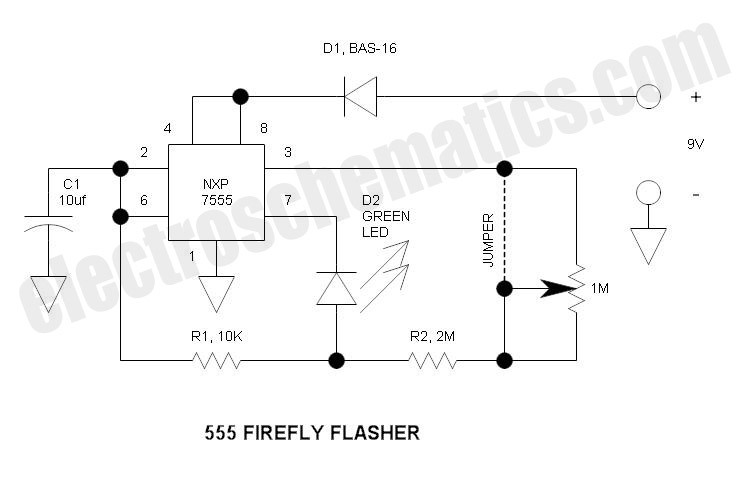
This circuit operates similarly to a standard 555 astable timer, with the distinction that the LED is integrated into the capacitor reset path. Consequently, when pin 7 discharges capacitor C1 to ground, a relatively high current flows through the...
This circuit is intended to drive the various lights decorating the crib prepared during Christmas season at many homes in Latin Countries, especially for children delight, in order to obtain realistic light-effects. The circuit design for driving lights in a...
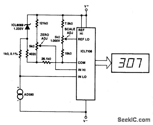
This circuit allows for zero adjustment as well as slope adjustment. The ICL8069 brings the input within the common-mode range, while the 5 K pots trim any offset at 218 °K (-55 °F) and set the scale factor. The...