
SSB ADAPTOR

To enable SSB reception on a standard AM shortwave receiver, modifications can be made to incorporate a beat frequency oscillator (BFO) circuit. The BFO generates a frequency that mixes with the incoming SSB signal, allowing the product detector to reconstruct the missing carrier wave, thereby enabling the listener to demodulate the SSB signal effectively.
The BFO circuit typically consists of a simple oscillator, which can be built using a transistor or an integrated circuit (IC). The oscillator frequency is set to a value close to the frequency of the incoming SSB signal, usually in the range of a few hundred hertz to a few kilohertz. This offset allows for proper demodulation of the SSB signal when it is mixed in the product detector.
In a basic schematic, the BFO output is fed into the mixer stage of the receiver, where it combines with the incoming SSB signal. The output of the mixer is then sent to a low-pass filter to remove unwanted high-frequency components, leaving the audio signal that can be amplified and sent to the speaker.
Additional components in the BFO circuit may include variable resistors for tuning, capacitors for stability, and possibly a diode for signal rectification. A potentiometer can be used to adjust the BFO frequency, allowing for fine-tuning to match the specific SSB signal being received.
Implementing a BFO in an AM receiver not only enhances its functionality but also significantly increases the range of signals that can be received and enjoyed by amateur radio operators and shortwave listeners. This modification is a cost-effective solution for those looking to explore the world of SSB communications without investing in more expensive dedicated SSB receivers.Most experienced amateurs know that SSB (single side band) reception requires a receiver fitted with a product detector or BFO (beat frequency oscillator) to reinsert the missing carrier. They also know that such receivers command significantly higher prices than AM only models. It is also a fact that signals broadcast using SSB tend to be far more interesting to amateurs and shortwave listeners than the standard AM broadcasts.
The problem is most readers only have a standard AM shortwave receiver - onet that is incapable of SSB reception. 🔗 External reference
Related Circuits

This direct-conversion receiver utilizes a TDA7000 integrated circuit (IC) and incorporates an LM386 audio amplifier. The TDA7000 serves as the mixer and local oscillator (L.O.) section. The frequency control can be achieved using either an air variable capacitor or...
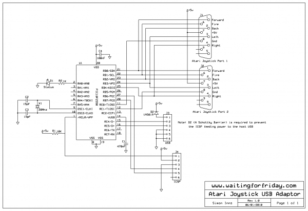
This project implements a composite USB device that supports two USB 2.0 full-speed gameport HID interfaces. The physical joystick ports are wired according to the Atari standard, allowing the connection of most Commodore 64 and Amiga joysticks, as well...
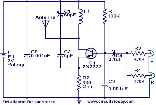
This compact FM adapter circuit, when connected to the audio output of a cassette player or iPod, enables the user to listen to their favorite music through a car stereo. It is particularly useful for vehicles that lack an...
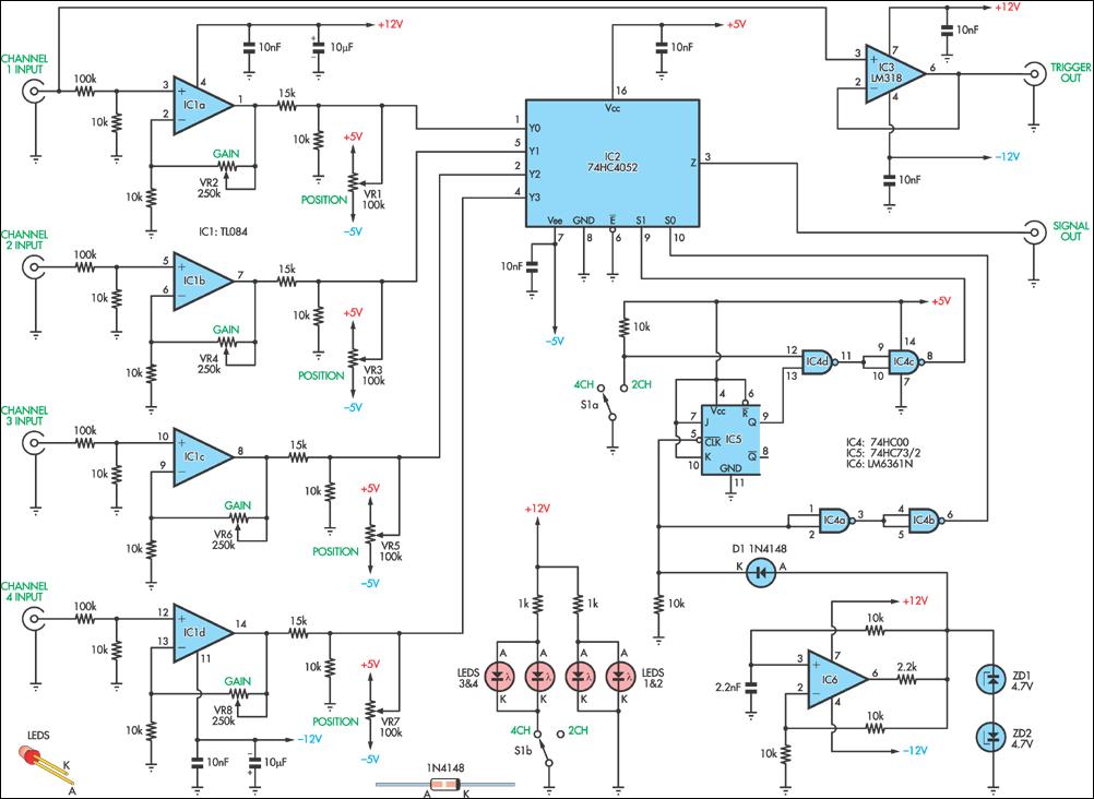
This circuit allows the simultaneous display of four signals using a single channel of an oscilloscope. It effectively switches each of the inputs to the oscilloscope. The circuit utilizes a multiplexer to manage the input signals. A typical configuration would...
This is a rather unusual QRP Power Amplifier design, with a wide frequency response; within three dB's from 300KHz to 30MHz. Overall gain is in the region of 16dB and the final output power may be well over four...
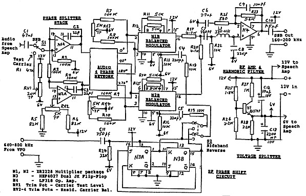
The circuit details are presented in Figure 3. The primary components of the system include a speech amplifier, an audio phase shift network with a balanced driver circuit (N1A, N2A), two balanced modulator stages (N1B & N2B), an RF...