
HF SSB CW AM RF Linear amplifier

The described QRP Power Amplifier (PA) is engineered for efficient operation across a wide frequency range, specifically from 300 kHz to 30 MHz, with a gain of approximately 16 dB. The design utilizes RF transformers T1 and T2, which are critical to achieving the amplifier's broad bandwidth. These transformers are constructed using two-hole ferrite balun cores, similar to those found in vintage valve television sets, which enhances their performance characteristics.
The winding process for the transformers involves twisting two lengths of 22 SWG enamelled wire together, which aids in reducing electromagnetic interference and improving coupling efficiency. The configuration requires connecting the end of the "A" winding to the beginning of the "B" winding, establishing a center-tap at this junction, which is essential for balanced operation.
This amplifier is capable of delivering a continuous output power of 4 watts when appropriately heat-sinked, making it robust enough for various applications, including outdoor or field operations. Its design allows for safe operation under load conditions that may otherwise damage typical amplifiers, such as short-circuit or open-circuit situations.
The circuit is versatile, supporting multiple modes of transmission, including Single Sideband (SSB), Continuous Wave (CW), and potentially Amplitude Modulation (AM). The adjustment of RV1 is crucial; it should initially be set to minimum resistance before applying a 12-volt power supply without any input drive. This configuration allows for the adjustment of the total supply current to approximately 250 mA. For applications requiring lower output power, the current can be reduced by decreasing the drive level, thus providing flexibility in operation.
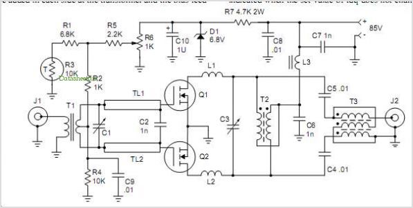
Overall, this QRP Power Amplifier design presents a unique solution for amateur radio enthusiasts seeking a reliable and efficient amplifier for various frequency bands and operational modes.This is a rather unusual QRP Power Amplifier design, with a wide frequency response; within three dB's from 300KHz to 30MHz. Overall gain is in the region of 16dB and the final output power may be well over four watts. The wide bandwidth is a result of the construction of the RF transformers, T1 and T2. These are wound on 2-hole ferrite balun cores as commonly found in the old fashioned valve TV sets (e.g.
Phillips 4322-020-31520). Twist 2 lengths of 22 SWG enamelled wire together and wind as shown. Connect the end of the "A" winding to the start of the "B" winding. Use this junction as the centre-tap of the transformer. This PA will deliver 4 watts continuously (with a suitable heatsink), and may be loaded into a short-circuit or open circuit without causing damage. This makes it almost the ideal PA for outdoor/field use. Above is the full circuit diagram of the RFPA and the coil winding pattern. This PA may be used for for SSB, as well as CW (and AM?). Set RV1 to MINIMUM resistance and apply 12volt power with NO DRIVE. Adjust RV1 for about 250mA DC total supply current. This may be be reduced to a much smaller current if lower output powers (reduced drive) is used. 🔗 External reference
Related Circuits

A constant current source is utilized in the differential amplifier circuit, which includes an emitter resistor. In this configuration, an increase in the output voltage (Ua) is not desirable. To ensure that Ua remains stable, the supply voltage (Ucc)...
The combination of controller IC LM4651 and LM4652 Class D MOSFET power amplifier IC provides a high-efficiency solution suitable for powered speakers, subwoofers, and car amplifiers. The LM4651 is a fully integrated conventional pulse width modulator (PWM) driver, which...
The microphone has high sensitivity in the audio range, but in the ultrasonic range, the sensitivity decreases rapidly. The receiver is very sensitive. To prevent overdriving and feedback due to the high sensitivity of the microphone in the audio...
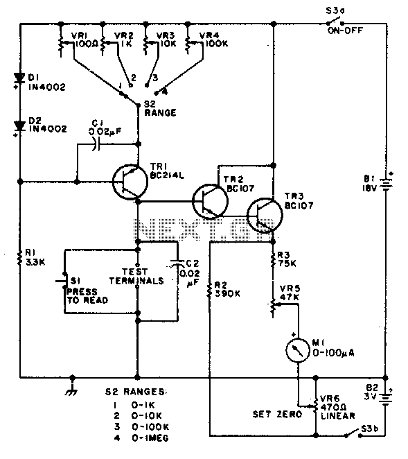
This circuit is designed to provide accurate measurement and a linear resistance scale at the high end. The circuit has four ranges. Additionally, another meter with a current range of 10 µA to 10 mA and a sensitivity of...
The converter depicted in Figure 1 utilizes a component from the PeakSwitch family (U1, a PKS606YN) to operate a 36 W motor, capable of handling startup and load transition peaks of up to 72 W. The motor speed can...
This FM RF amplifier utilizes two transistors from Philips: the BLV 10 and the BLW 87. The two RF transistors are configured in a chic C arrangement, providing an overall gain of 21 dB (100 times) with an efficiency...