
stable fm transmitter

The described FM transmitter circuit is designed for reliability and ease of assembly, making it suitable for hobbyists and educational projects. The use of a zener diode is crucial, as it stabilizes the voltage supplied to the oscillator, ensuring consistent performance even as the battery voltage diminishes. This feature is particularly important in applications where frequency stability is critical, such as in communication systems.
The coil L, wound with #22 enameled wire, serves as a critical component in the oscillator circuit. The specified number of turns (8 to 10) and the diameter of the coil form (6.30 mm) are optimized for achieving the desired frequency range while maintaining a manageable size for the overall circuit. The choice of wire gauge ensures that the coil can handle the RF currents without overheating, while the enameled insulation provides necessary electrical isolation.
Powering the circuit with either 9 or 12 volts DC provides flexibility in operation, allowing users to select a suitable power source based on availability and requirements. The recommendation to keep components in close proximity aids in minimizing signal loss and interference, which can significantly affect performance.
The antenna design is another critical aspect of the circuit. A 12-inch wire antenna is suitable for short-range applications, while a 30-inch antenna can enhance transmission range, making it more effective for longer distances. For users seeking even greater range, constructing a DIY FM antenna can further improve the transmitter's capabilities. This could involve using a dipole or a ground plane antenna design, which can be tailored to the specific frequency of operation for optimal performance.
Overall, this FM transmitter circuit exemplifies a straightforward yet effective approach to building a stable transmission system, suitable for various applications in radio communication.There are many techniques to make an FM transmitter stable so it will not change its frequency as the battery runs down. The rf circuit shown below is a mini stable FM transmitter which is using a zener diode to provide accurate voltage to the oscillator while the battery runs down, due to which it will not drift its frequency.
The circuit is simp le using few components but provide good range. The coil L is equal to 8 to 10 turns of #22 enameled wire wound on 6. 30 millimeters diameter form. The input voltage can be 9 or 12 volts DC. Keep all the components as near as possible and use 12 inch wire for antenna or use 30 inch wire antenna for greater range. If you require a long range with this circuit use diy fm antenna. 🔗 External reference
Related Circuits
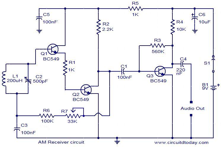
Circuit diagram of a modulator circuit in a transmitter and receiver of amplitude modulation. The modulator circuit in an amplitude modulation (AM) transmitter and receiver plays a crucial role in the process of encoding information onto a carrier wave. In...
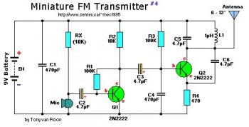
This small FM band transmitter utilizes only two 2N2222 transistors and is capable of transmitting signals up to 1 kilometer away, provided there are no obstacles between the two antennas. The circuit features a microphone preamplifier stage with the...
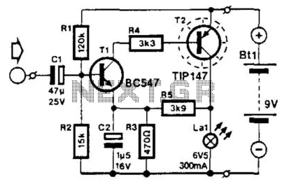
This circuit modulates the current through a lamp filament. It is designed for use with a low-voltage lamp featuring a thin, straight filament, which responds quickly to variations in filament voltage. Direct current (DC) is applied to bias the...

A positive-going trigger pulse can be used to initiate the timing cycle with the circuit shown. In this design, trigger input pin 2 is biased to 6V by divider R1 and R2. Control input pin 5 is biased to...
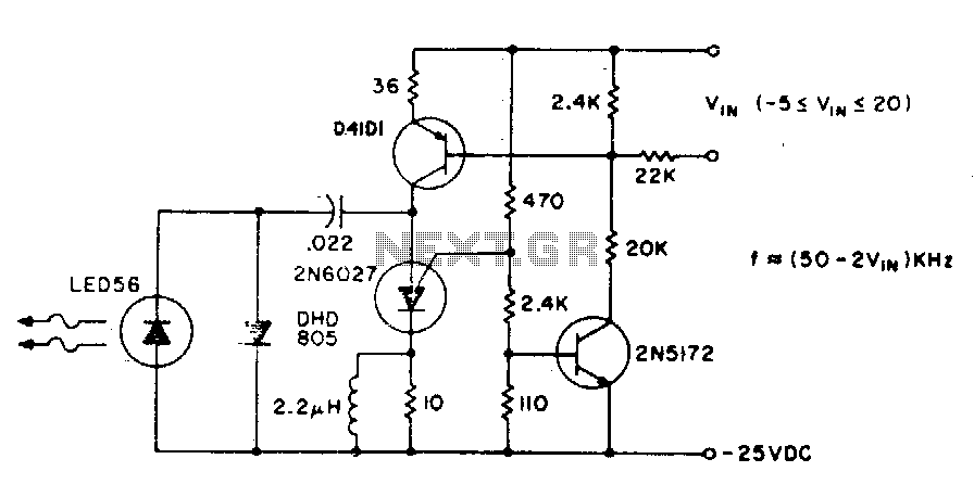
The basic circuit operates at a frequency of 80 kHz, which is constrained by the combination of the PUT (Programmable Unijunction Transistor) capacitors. The maximum modulation frequency achievable is 60 kHz. The pulse repetition rate is directly proportional to...
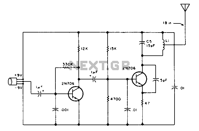
This transmitter can be tuned to the FM broadcast band, 2 meters, or other VHF bands by changing C5 and L1. The values provided for C5 and L1 will position the frequency within the FM broadcast band. L1 consists...