
FM (prm) optical transmitter
 optical transmitter")
The described circuit is a frequency-modulated transmitter designed for applications requiring precise control over output characteristics. Operating at a fundamental frequency of 80 kHz, the circuit's performance is primarily dictated by the selected PUT capacitor arrangement. The modulation frequency is capped at 60 kHz, which is a critical parameter for ensuring signal integrity and minimizing distortion during transmission.
The relationship between the pulse repetition rate and the modulating voltage (Vin) indicates that the circuit is capable of dynamic adjustments based on input conditions. This feature allows for flexibility in various operating environments, making it suitable for applications that require adaptive modulation.
To mitigate stray light interference, the incorporation of optical components such as lenses or reflectors is essential. These components enhance the signal-to-noise ratio by directing the emitted infrared light more effectively and reducing ambient light interference.
For applications demanding higher output levels, two primary methods can be employed. The first method involves increasing the capacitance of the PUT capacitors, which not only boosts output but also lowers the operating frequency. The second method consists of selecting a higher power output IRED, such as the F5D1, which is designed to provide enhanced performance and efficiency in infrared transmission.
The circuit's average power consumption, which remains below 3 watts, indicates a design that is energy-efficient while still delivering adequate performance for its intended applications. This low power requirement is advantageous for battery-operated devices or systems where power availability is limited, thereby extending operational longevity without compromising functionality. Overall, this circuit design exemplifies a balance between performance, adaptability, and efficiency, suitable for a range of electronic applications.The basic circuit can be operated at 80 kHz and is limited by the PUT capacitor combination. 60 kHz is the maximum modulation frequency. The pulse repetition rate is a linear function of Vin, the modulating voltage. Lenses or reflectors minimizes stray light noise effects. Greater output can be obtained by using a larger capacitor, which also gives a lower operating frequency, or using a higher power output IRED such as the F5D1 Average power consumption of the transmitter circuit is less than 3 watts.
Related Circuits
This circuit is a simple two-transistor (2N2222) mini FM transmitter. No authorization is required for this transmitter according to FCC regulations regarding wireless microphones. When powered by a 9-volt battery and equipped with an antenna no longer than 12...
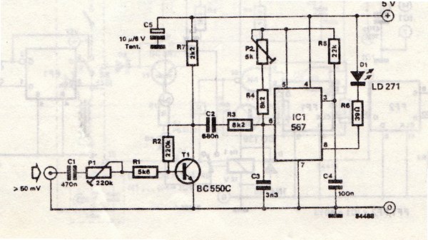
The transmitter is equipped with an LM567 tone decoder circuit. An audio signal (at least 50 mV peak-to-peak) is amplified with a transistor (T1) and then used to modulate IC1. The infrared transmitter frequency is adjusted with potentiometer P2...
Operating radio transmitters without a license is illegal in most countries, so caution is advised with transmitter circuits. This FM low-power circuit is designed to operate within the 87-108 MHz band II, providing a range of approximately 20 to...
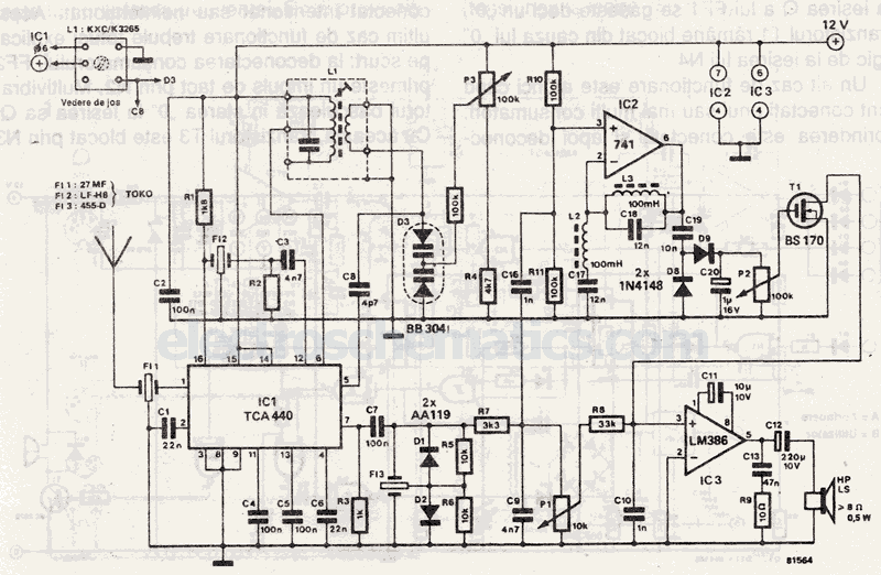
Narrow Band Frequency Modulation (NBFM) is utilized in this 27 MHz transmitter circuit schematic. This circuit is based on the Motorola MC2833 VHF transmitter, which integrates FM modulation and narrow band capabilities into a single chip. P1 is designated...
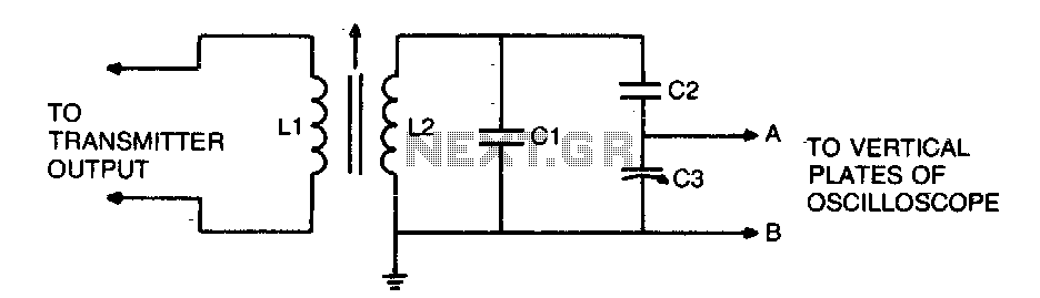
To display an RF signal, connect LI to the transmitter and points A and B to the vertical plates of the oscilloscope. Adjust LI for minimum SWR and C3 for the desired trace height on the CRT. More: L2...
This ZIP file contains information about building a small radio transmitter, which has a PCB 1.75" x 2.5" (45mm x 68 mm) and has a range of about 30 yards or so. The documentation with the circuit says the...