
555 IC For Basic Monostable Multivibrator

The basic monostable multivibrator circuit using the 555 Timer IC operates by producing a single output pulse in response to a triggering input. When the trigger pin (pin 2) receives a negative pulse, the output (pin 3) goes high for a duration determined by the resistor (R1) and capacitor (C1) values. The time period of the output pulse can be calculated using the formula t = 1.1 x R1 x C1, where t is the pulse width in seconds, R1 is in ohms, and C1 is in farads.
In this configuration, pin 4 serves as the RESET pin, allowing the circuit to be reset and the output pulse to be terminated prematurely if needed. The 555 Timer can be powered by a standard DC supply, typically between 5V and 15V, depending on the specific requirements of the application.
The circuit typically includes a diode connected in parallel with the timing capacitor to discharge it quickly when the output goes low, ensuring reliable operation. The design can be adapted for various applications, such as timers, pulse generators, or frequency dividers, by adjusting the values of R1 and C1.
In practical applications, it is essential to consider the tolerance of the resistor and capacitor, as variations can significantly affect the timing accuracy. Additionally, bypass capacitors may be included near the power supply pins to filter out noise and ensure stable operation of the 555 Timer IC.Description:The following circuit shows about Basic Monostable Multivibrator. This circuit based on the 555 Timer IC. Features: Pin 4 is the RESET, t=R1xC1, .. 🔗 External reference
Related Circuits
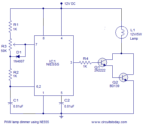
A simple PWM lamp dimmer using the NE555 timer IC. The 555 timer IC is configured as a variable duty cycle astable multivibrator to control the brightness of the lamp. The described circuit utilizes the NE555 timer IC, a versatile...
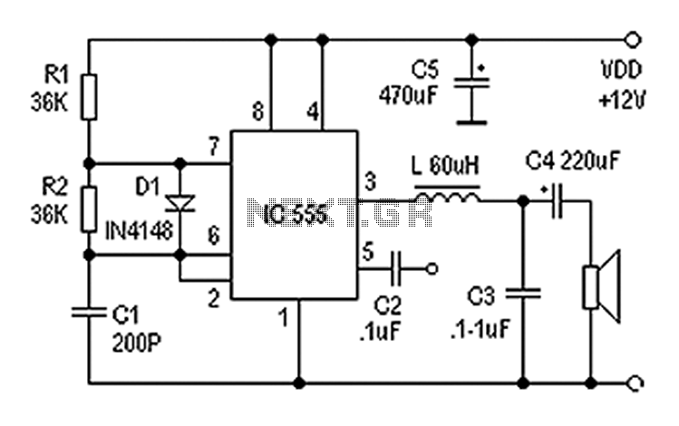
Also known as a digital amplifier, the Class-D amplifier is characterized by its compact size and high efficiency. This circuit utilizes a 555 timer IC to create a Class D amplifier. The 555 timer operates as a controllable multivibrator,...
A project of a 555 tester circuit, the circuit will start blinking LEDs when power is applied, which will indicate that the IC is working correctly. The 555 tester circuit is designed to verify the operational status of the 555...
The primary components of this doorbell circuit include two NE555 timer integrated circuits (ICs). When the switch S1 is pressed momentarily, the loudspeaker emits a bell tone for the duration determined by the time period of the monostable multivibrator...

This is a circuit for a mosquito repellent that operates using high-frequency sound. It utilizes commonly available and low-cost electronic components. The circuit includes integrated circuits such as the IC 555 and 4017. The mosquito repellent circuit employs a high-frequency...
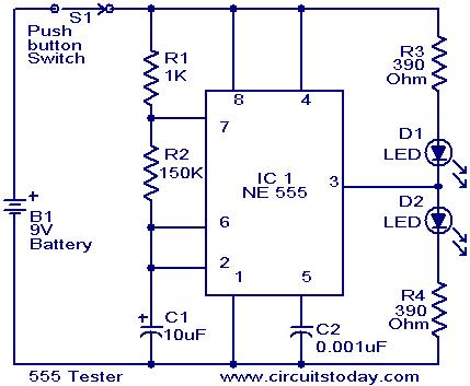
The NE555 timer is configured as an astable multivibrator. When the push button switch S1 is pressed, the LEDs D1 and D2 will flash alternately. When the output is high, D2 will illuminate, and when the output is low,...