
Stable Vfo

The VFO (Voltage Controlled Oscillator) circuit is a crucial component in many RF applications, particularly in communication systems where precise frequency generation is essential. This specific VFO circuit is designed to cover a frequency range from 2.13 MHz to 2.58 MHz, making it suitable for various amateur radio and commercial applications. The ability to heterodyne the generated signal with an external mixer allows for the creation of intermediate frequencies that can be processed further in a receiver or transmitter.
The circuit's output power levels are significant for ensuring compatibility with various mixing stages. The output from Q3, which delivers a power range of 0 to +3 dBm, is adequate for low-level mixing applications. However, for high-level mixing, Q4 acts as a Class A power amplifier, providing a substantial increase in output power to +22 dBm. This higher power level is necessary for driving high-level mixers that require stronger input signals to maintain signal integrity and minimize distortion.
The design includes specific coil data, which is essential for tuning the VFO to the desired frequency. The parts list should detail the inductance values and specifications for the coils used in the circuit, as these components directly influence the oscillation frequency. Additionally, the circuit's versatility allows for operation at other frequencies through suitable component changes, which could involve adjusting capacitor values or replacing inductors, as suggested in the provided table.
In summary, this VFO circuit is a well-engineered solution for generating RF signals in the specified frequency range, with robust output capabilities and flexibility for tuning to other frequencies. The integration with an external mixer further enhances its utility in a variety of electronic communication applications. This VFO circuit covers from 2.13 to 2.58 MHz and is intended for use with an external mixer to heterodyne the signal to desired frequencies. Coil data is shown in the parts list. Two power output levels are available—a few hundred mW (0 to +3 dbm) from Q3. Q4 is a class A amplifier for boosting the power to +22 dbm for driving a high-level mixer. The VFO can be operated on other frequencies, with suitable component charges (see the table). 🔗 External reference
Related Circuits
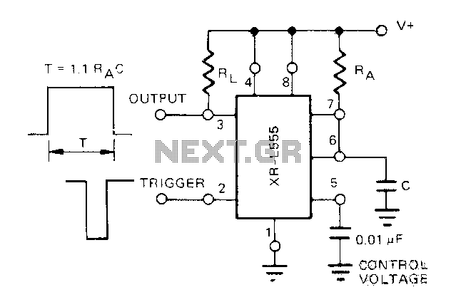
The Exars XR-L555 circuit has a typical power consumption of 900 W and operates with a power supply voltage of 5V. It is a micro-power circuit that can be used as a direct replacement for the standard 555 timer....
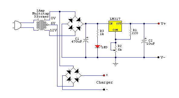
The purpose of a DC power supply is to deliver the necessary level of DC power to a load by utilizing an AC supply at the input. Various applications demand different specifications; however, contemporary DC power supplies often ensure...
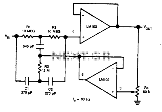
In applications where the rejected signal may slightly deviate from the null point in a notch network, it is beneficial to decrease the Q factor of the network. This adjustment ensures consistent rejection across a broader range of input...
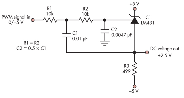
This simple circuit converts a 5V PWM signal into a variable precision reference voltage with a range of -2.5V to +2.5V. Many designs, such as a digitally controlled power supply or a programmable dummy load, require a Digital to...
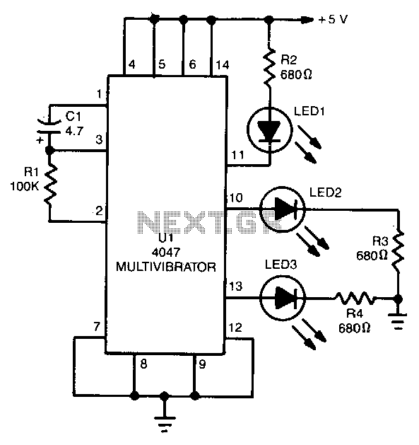
The 4047 is configured as a free-running astable multivibrator (oscillator) circuit. This configuration offers three different outputs. The output pulses at the Q and Q output (pins 10 and 11, respectively) are the same as in the previous two...

The schematic for a monostable multivibrator is presented below. Similar to the astable multivibrator, one transistor conducts while the other cuts off when the circuit is powered. It is important to note that, unlike the astable multivibrator, the one-shot...
Warning: include(partials/cookie-banner.php): Failed to open stream: Permission denied in /var/www/html/nextgr/view-circuit.php on line 713
Warning: include(): Failed opening 'partials/cookie-banner.php' for inclusion (include_path='.:/usr/share/php') in /var/www/html/nextgr/view-circuit.php on line 713