
Micropower monostable circuit diagram

The Exars XR-L555 is a versatile timer circuit designed for low-power applications. With a power consumption of 900 W, it is optimized for efficiency, making it suitable for battery-operated devices. The circuit operates at a supply voltage of 5V, allowing it to be integrated into various electronic systems that require a reliable timing mechanism.
The XR-L555 functions similarly to the classic 555 timer, providing the same timing capabilities with enhanced performance characteristics. The timing interval is adjustable through the selection of an external resistor (RA) and capacitor (C). The relationship between these components is defined by the formula:
\[ T = 1.1 \times RA \times C \]
where \( T \) is the output pulse duration. By varying the values of RA and C, users can precisely control the timing behavior of the circuit, making it suitable for applications such as pulse width modulation, timer delays, and oscillators.
In addition to its basic timing functions, the XR-L555 may also include features such as a low-power sleep mode, which further enhances its efficiency in power-sensitive applications. The micro-power design ensures that the circuit consumes minimal energy during operation, making it an ideal choice for portable and battery-operated devices.
Overall, the Exars XR-L555 circuit combines the familiar functionality of the traditional 555 timer with modern enhancements that cater to low-power requirements, providing a reliable and flexible solution for a wide range of electronic timing applications.Exars XR-L555 circuit typical power consumption is 900 W, the power supply voltage of 5V, micro-power circuit, XR-L555 can be used directly in place of the 555 timer. Delay by an external resistor and a capacitor (RA and C) control, delay determines the duration of the output pulse.
Related Circuits
The digital scoreboard circuit is designed to display numerical values ranging from 0 to 9 on a common anode 7-segment display. The circuit employs a 7-segment driver integrated circuit (IC), specifically the 74LS47 or 74LS247. A 555 timer IC...
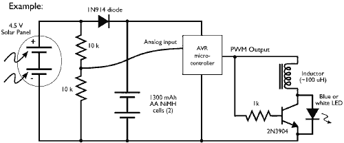
This example demonstrates the PWM (pulse-width modulation) output of a microcontroller controlling a Joule Thief style voltage booster to power a white LED. The circuit described utilizes a microcontroller to generate a PWM signal, which is an effective method for...
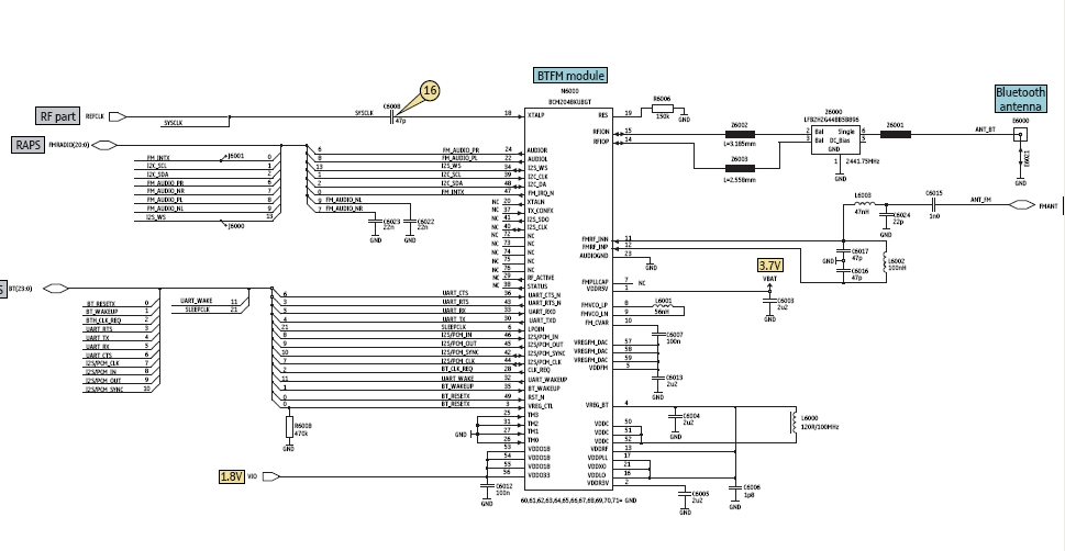
Bluetooth is an open wireless technology standard for exchanging data over short distances between fixed and mobile devices, utilizing short wavelength radio transmissions to create personal area networks (PANs) with high security. The Bluetooth baseband protocol combines circuit and...
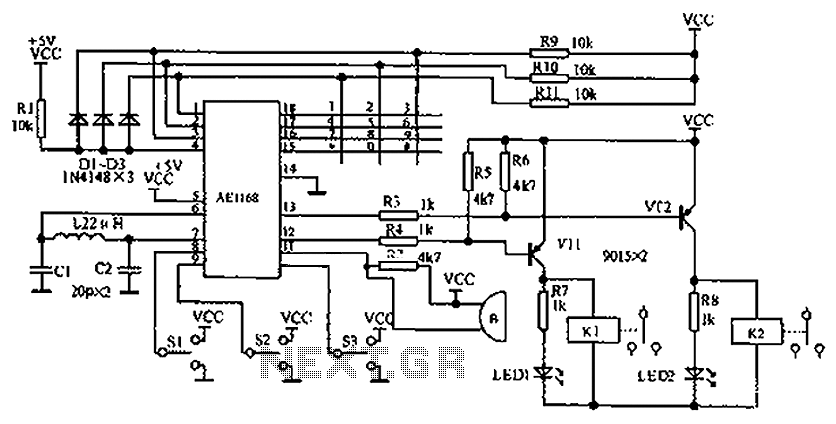
The circuit diagram represents an enhanced lock system, the AE1169, which is an upgrade of the AE1168 model. When the lock button is pressed, the AE1168 utilizes a keyboard scanning method to identify the corresponding button. Based on the...
Variable resistor R1 adjusts the light threshold at which the circuit triggers. R1's value is chosen to match the photocell's resistance at darkness. The circuit uses a CMOS 4001 IC. Gate U1a acts as the trigger, U1b and c...

This circuit has the advantage of transferring almost all the energy from the collapsing magnetic field of L2 to C2. In contrast, a typical Joule thief circuit allows some of this energy to return to the battery. This efficiency...