
Stand alone CDROM audio driver

The circuit described facilitates the operation of a CD-ROM drive as a standalone audio player by providing the necessary power supply. The power supply circuit is designed to output +5V and +12V, along with a ground connection, which are standard voltage requirements for most CD-ROM drives. The use of a D-type power connector is crucial for establishing a secure and reliable connection between the power supply circuit and the CD-ROM drive.
The D-connector is designed to fit into the CD-ROM in a single orientation, which serves as a safeguard against incorrect connections that could lead to potential damage. This feature enhances the user experience by simplifying the setup process and ensuring the device operates safely.
When connecting the D-connector, it is essential to observe the color coding of the wires: the yellow wire, which carries the +12V supply, must be positioned correctly to the right side of the connector when viewed from the rear, with the connector's curved portion oriented upwards. This attention to detail is critical in maintaining the integrity of the circuit and ensuring proper functionality.
Upon inserting an audio CD into the drive, the playback begins automatically, allowing users to enjoy their music without needing to interface with a computer. The front panel of the CD-ROM drive typically includes a Skip-Track button, which provides a simple means for users to navigate through the audio tracks. This design emphasizes user convenience and accessibility, making it an effective solution for those wishing to utilize their CD-ROM drives for audio playback independently.Most of the CDROMS available have an Audio-Out Output to either plug in the headphones or connect it to an amplifier. This circuit enables one to use the CDROM as a stand alone Audio CD player without the computer. This circuit is nothing but a power supply which supplies +5v, +12V and Ground to the CDROM drive and hence can be used without the computer.
You should buy a D-type power connecter to connect this circuit's outputs to the CDROM. The details of the D connector are shown along with the circuit diagram. Note that the D-connector goes into the CDROM in only one way and hence prevents any damage due to wrong connection. Ensure that the 12V(yellow) wire is connected to the right of the D-connector(as seen from behind ,i.e the connector holes away from you with the curved portion of the connector upwards) As soon as an Audio CD is inserted, the CD begins to play.
To move to the next track, press the Skip-Track button on the CDROM front Panel. 🔗 External reference
Related Circuits
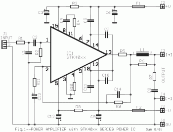
This is a power audio amplifier circuit based on the STK400xx series. It provides high-quality sound and is cost-effective, as the STK40xx series is affordably priced. The circuit can be easily constructed using only a few external components. The...
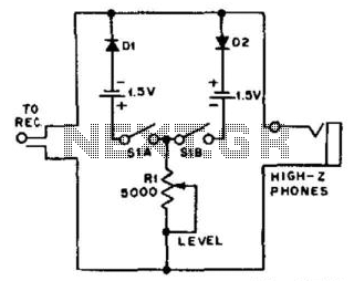
For use with headphones, this circuit sets the audio clipping level via a 5-kOhm potentiometer. This type of noise clipper is most effective for pulse-type noise with a low duty cycle, such as ignition noise. The resistor Rl establishes...
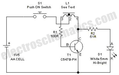
This simple LED driver circuit allows the operation of up to seven LEDs using a single NiMH (Nickel Metal Hydride) AA cell. The circuit generates voltage pulses. The LED driver circuit is designed to efficiently power multiple LEDs while maintaining...
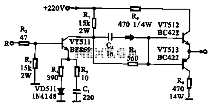
The CRT final video driver amplifier is a complementary push-pull final video driver amplifier composed of three transistors. VT511 functions as a driver amplifier, utilizing a common emitter configuration that offers high gain characteristics. The input signal from the...

This page outlines a project that utilizes an audio signal to control an RC servo. The movement of the servo is proportional to the loudness of the sound. This concept is particularly applicable for creating animated mouths for talking...

Often, there is a need for an additional telephone ringer in an adjoining room to be alerted about incoming calls. For instance, if the telephone is situated in the drawing room, an extra ringer may be required in the...