
LED Driver Circuit with 555 Timer

The LED driver circuit is designed to efficiently power multiple LEDs while maintaining optimal performance and longevity of the components involved. The core of the circuit is typically based on a switching regulator or a simple transistor-based design that enables the control of current flowing through the LEDs.
In this configuration, a single NiMH AA cell provides the necessary voltage and current. The circuit may include a resistor to limit the current to the LEDs, ensuring that they do not exceed their rated specifications, which can lead to thermal runaway and eventual failure.
The switching regulator may consist of a transistor, such as an N-channel MOSFET, which acts as a switch that turns on and off rapidly, creating a pulse-width modulation (PWM) effect. This method allows for efficient power management, reducing heat generation and improving battery life.
An additional component, such as a capacitor, may be included in the circuit to smooth out the voltage and provide a stable power supply to the LEDs. This capacitor helps to maintain a consistent brightness level, even when the load changes or the battery voltage drops as it discharges.
The arrangement of the LEDs can be in series or parallel, depending on the desired brightness and forward voltage requirements. If arranged in series, the total forward voltage drop must be considered to ensure it does not exceed the supply voltage. Conversely, if arranged in parallel, each LED should have its own current-limiting resistor to ensure even distribution of current.
Overall, this LED driver circuit exemplifies a practical application of basic electronic components to achieve efficient and effective illumination solutions using minimal power resources.This simple LED driver circuit allows us to drive up to seven LEDs by using a single NiMH (Nickel Metal Hydride) AA cell. The circuit produces voltage puls.. 🔗 External reference
Related Circuits
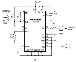
A high-frequency waveform generator is highly beneficial for electronic experimentation and design. This circuit generates sine wave oscillations; however, it can be modified to produce triangle or square wave functions. The frequency can be controlled using current. By disconnecting...
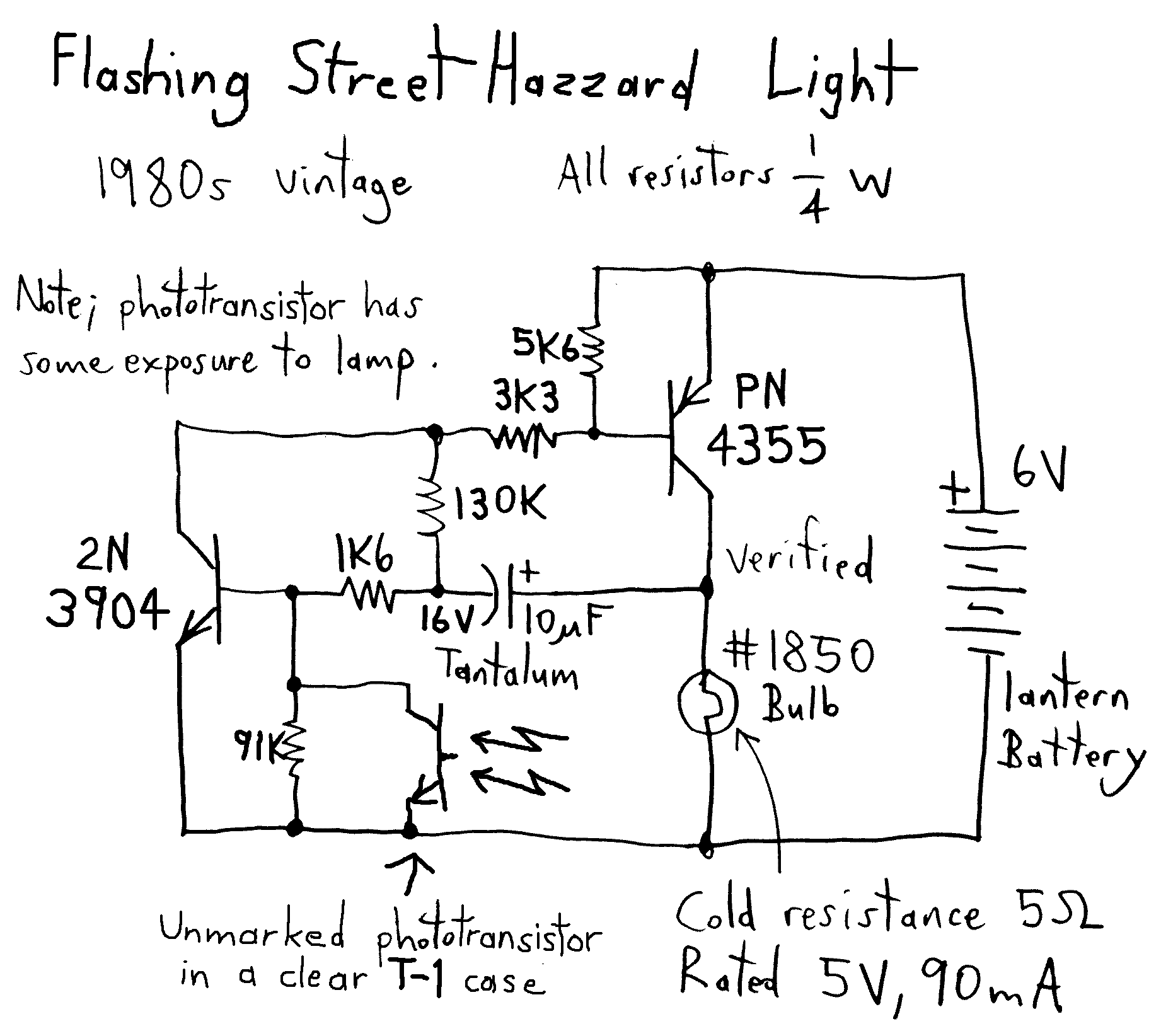
This is a reverse-engineered circuit diagram of a one-transistor circuit commonly used to drive permanent magnet DC motors in children's toys. This circuit typically employs the 625mW version of the widely used 8050 or 8550 transistor. It is important...
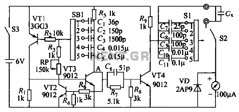
A capacitive measuring instrument is a direct reading device that measures the capacitance of a circuit. This instrument is capable of measuring capacitance values ranging from a few picofarads to 0.1 microfarads, with specific ranges of 25 pF, 100...
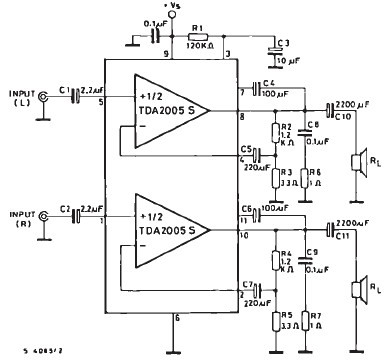
The TDA2005 car audio amplifier circuit is specifically designed for use in devices such as car radios, CD players, and similar equipment. This amplifier is based on the TDA2005 audio integrated circuit (IC), capable of delivering a maximum output...
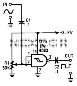
This circuit converts a sine wave into a square wave. It consists of a single 2-input NAND Schmitt trigger configured as an inverter, with an adjustable trigger level at its input. As the input voltage exceeds the gate's trigger...
Locker Guard Circuit Diagram. This compact circuit is designed to protect a locker or almirah from burglary. If the locker is opened while in the armed state, the circuit triggers a loud police siren to deter the burglary attempt. The...