
static 0 to 9 display

This circuit is designed to effectively showcase numerical values from 0 to 9 using a seven-segment display, which is a common requirement in digital electronics for applications such as timers, counters, and simple user interfaces. The asynchronous decade counter (7490) is a binary-coded decimal (BCD) counter that counts from 0 to 9 and then resets to 0 upon reaching 10, making it ideal for this application.
The seven-segment display is composed of seven individual LEDs arranged in a figure-eight pattern, allowing for the representation of decimal digits. The common anode configuration means that all anodes of the LEDs are connected to a positive voltage, while the individual cathodes are connected to ground through current-limiting resistors (R1 to R7). These resistors are critical in preventing excess current from flowing through the LEDs, thereby ensuring their longevity and proper operation.
The decoder/driver IC (7446) takes the BCD output from the 7490 counter and converts it into the appropriate signals required to illuminate the correct segments of the display. Each output from the 7446 corresponds to a specific digit, illuminating the necessary segments to form that digit visually.
Clock pulses, which can be generated by an external clock circuit or a microcontroller, provide the timing mechanism for the counter. Each pulse increments the counter, and the decoder interprets the new state of the counter to update the display accordingly. This seamless interaction between the counter, decoder, and display allows for a clear and immediate visual representation of the counted value, making it a versatile solution for various electronic projects requiring numerical output.The circuit shown here is of a simple 0 to 9 display that can be employed in a lot of applications. The circuit is based on asynchronous decade counter 7490(IC2), a 7 segment display (D1), and a seven segment decoder/driver IC 7446 (IC1). The seven segment display consists of 7 LEDs labelled a` through g`. By forward biasing different LEDs, we can display the digits 0 through 9. Seven segment displays are of two types, common cathode and common anode. In common anode type anodes of all the seven LEDs are tied together, while in common cathode type all cathodes are tied together. The seven segment display used here is a common anode type. Resistor R1 to R7 are current limiting resistors. IC 7446 is a decoder/driver IC used to drive the seven segment display. Working of this circuit is very simple. For every clock pulse the BCD output of the IC2 (7490) will advance by one bit. The IC1 (7446) will decode this BCD output to corresponding the seven segment form and will drive the display to indicate the corresponding digit.
🔗 External reference
Related Circuits
As equipment becomes increasingly compact, designers are often required to reduce the size of displays. However, this can compromise the usefulness of the display. Many individuals find it challenging to read small displays, which can be particularly frustrating. In...
This circuit is suitable for a small office or home environment. It can also be adapted to use a combination lock or keypad for setting and resetting. The described circuit functions as a security system tailored for small office or...
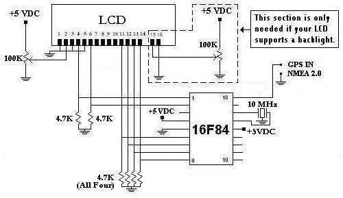
This is a project that I started back late 2003 when I just starting to learn PIC programming. I wanted to building something that actually did something useful. This project is based on a PIC16F84. I actually came up...
A segment can be tested by applying an alternating voltage of a few volts across it. It is important to note that applying a direct voltage can cause irreversible damage to the display, as the resulting current will remove...
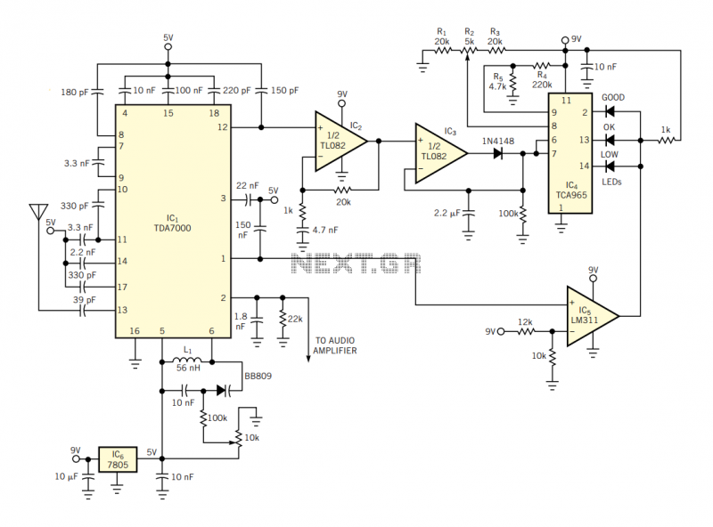
The IC has an FLL (frequency-locked-loop) structure. The filtered output of the FM discriminator frequency-modulates the local oscillator to provide negative-feedback modulation. The result is compression of the signal at the output of the mixer. Thus, the IF bandpass...
Each part of the LCD has an individual counter, latch, decoder, and driver. The pumping signal is fed back to the motherboard of the LCD. When the display section is disconnected, the phase and amplitude of the motherboard and...