
Static 0 to 9 display

The circuit operates using a clock signal that provides timing for the asynchronous decade counter (7490). The 7490 is configured to count from 0 to 9 in binary-coded decimal (BCD) format. Each output pin of the 7490 corresponds to a specific bit in the BCD representation of the decimal digits. When the clock pulse is applied, the counter increments its count, and the output state changes accordingly.
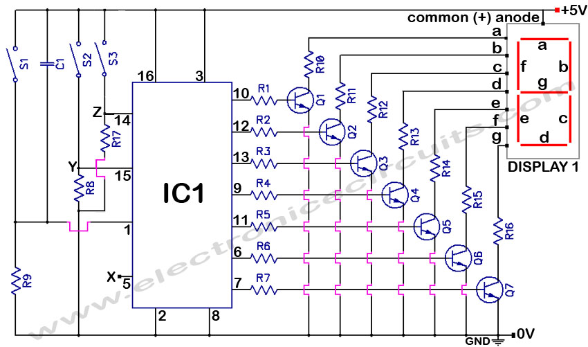
The seven-segment display, being of the common anode type, requires that the anodes of each LED segment be connected to a positive voltage supply. The cathodes of the LEDs are connected through current-limiting resistors (R1 to R7) to the output pins of the decoder/driver IC (7446). The resistors are crucial for preventing excessive current from flowing through the LEDs, thus protecting them from damage and ensuring optimal brightness.
The 7446 decoder/driver interprets the BCD output from the 7490 and activates the appropriate segments of the display to form the corresponding digit. Each output pin of the 7446 is connected to the respective segments of the display. For instance, if the BCD output corresponds to the digit '3', the decoder will activate segments 'a', 'b', 'c', 'd', and 'g' of the display, illuminating them to visually represent the number '3'.
This circuit can be employed in various applications, including digital counters, scoreboards, and other devices requiring numerical display. The simplicity of the design and the availability of the components make it an ideal choice for educational purposes and basic electronic projects.The circuit shown here is of a simple 0 to 9 display that can be employed in a lot of applications. The circuit is based on asynchronous decade counter 7490(IC2), a 7 segment display (D1), and a seven segment decoder/driver IC 7446 (IC1). The seven segment display consists of 7 LEDs labelled a` through g`. By forward biasing different LEDs, we can display the digits 0 through 9. Seven segment displays are of two types, common cathode and common anode. In common anode type anodes of all the seven LEDs are tied together, while in common cathode type all cathodes are tied together. The seven segment display used here is a common anode type. Resistor R1 to R7 are current limiting resistors. IC 7446 is a decoder/driver IC used to drive the seven segment display. Working of this circuit is very simple. For every clock pulse the BCD output of the IC2 (7490) will advance by one bit. The IC1 (7446) will decode this BCD output to corresponding the seven segment form and will drive the display to indicate the corresponding digit.
🔗 External reference
Related Circuits
4033 7 Segment Common Anode Display Event Counter Circuit. This circuit can count from 0 to 9 with a reset function and a display test feature. The 4033 7-segment common anode display event counter circuit is designed to count events...

The circuit is constructed using the ICM7217 integrated circuit from Intersil, which features a CMOS up/down counter with a four-digit display. The clock generator circuit, IC3, produces a square wave clock signal with a period of one second, available...
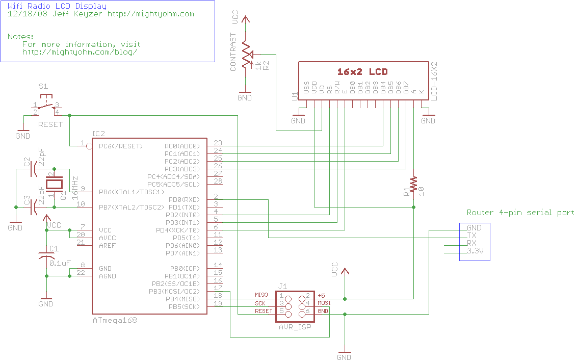
This is the seventh part of an ongoing series about building a low-cost, open-source streaming internet radio. If you have not already, check out the previous parts for some background about the project. In part six, UNIX-style shell commands...
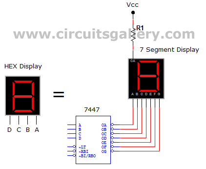
This circuit defines seven levels in a reservoir. The sensed values are connected to an encoder circuit, which consists of a 74148 integrated circuit (IC), functioning as an 8-line to 3-line encoder. The next section features a HEX display,...
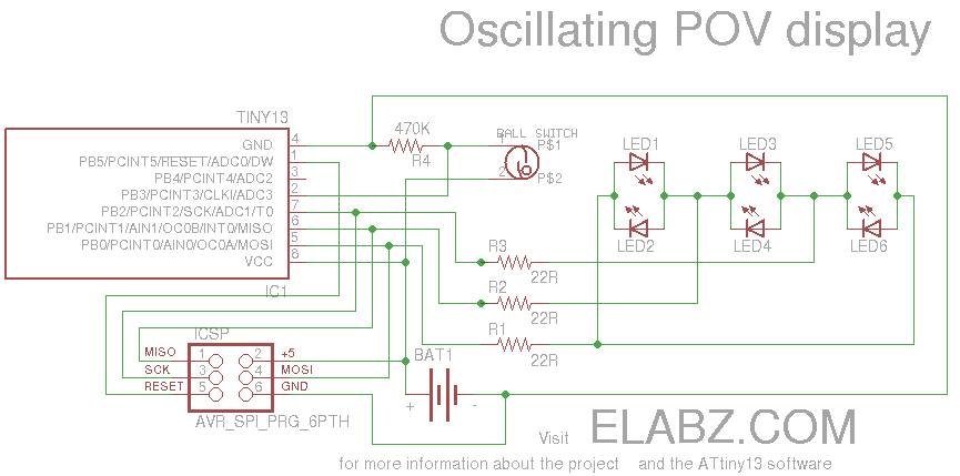
Smart Valentine's Day gift - a movement-sensing box of chocolates with an LED message. Circuit diagram and instructions for building the project using ATtiny13 and Arduino. The project involves creating a movement-sensing box of chocolates that incorporates an LED display...
A 4511 integrated circuit (IC) has been utilized to display numbers 1-9 on a seven-segment LED display. The objective is to explore methods to extend this functionality to display additional numbers. The CD4511 is a BCD to 7-segment latch decoder/driver...