
Valentines Day POV display using ATtiny13 and Arduino IDE

The project involves creating a movement-sensing box of chocolates that incorporates an LED display to convey a message, making it an innovative gift for Valentine's Day. The design utilizes an ATtiny13 microcontroller, which is suitable for low-power applications, and an Arduino platform for ease of programming and prototyping.
The circuit consists of the following key components:
1. **ATtiny13 Microcontroller**: This serves as the main controller for the project. It is responsible for processing input from the motion sensor and controlling the output to the LED display.
2. **Motion Sensor**: A passive infrared (PIR) sensor or an accelerometer can be used to detect movement. When motion is detected, the microcontroller triggers the LED display to light up with a pre-programmed message.
3. **LED Display**: A series of LEDs or a small LED matrix can be employed to display the message. The choice of display will affect the complexity of the circuit and the programming required.
4. **Power Supply**: A battery pack or USB power source can be used to power the circuit. The ATtiny13 is designed for low power consumption, which is ideal for battery-powered applications.
5. **Resistors and Capacitors**: These components are necessary for current limiting and signal smoothing, ensuring that the microcontroller operates reliably.
The circuit can be built on a breadboard for initial testing before being finalized onto a printed circuit board (PCB). The programming is typically done using the Arduino IDE, which allows for easy integration of libraries for handling the LED display and motion sensor.
In summary, the movement-sensing box of chocolates combines simple electronics with creative design to produce a unique Valentine's Day gift. The project encourages exploration of microcontroller programming and circuit design, making it suitable for both beginners and experienced hobbyists.Smart Valentine`s Day gift - a movement-sensing box of chocolates with an LED message! Circuit diagram and How to build the project on ATtiny13 and Arduino. 🔗 External reference
Related Circuits
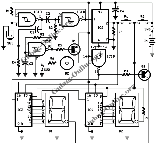
This design features a signal logic tester that utilizes a common cathode seven-segment display. The display indicates a logic level "1" (represented by an "H" on the display) or a logic level "0" (represented by an "L" on the...
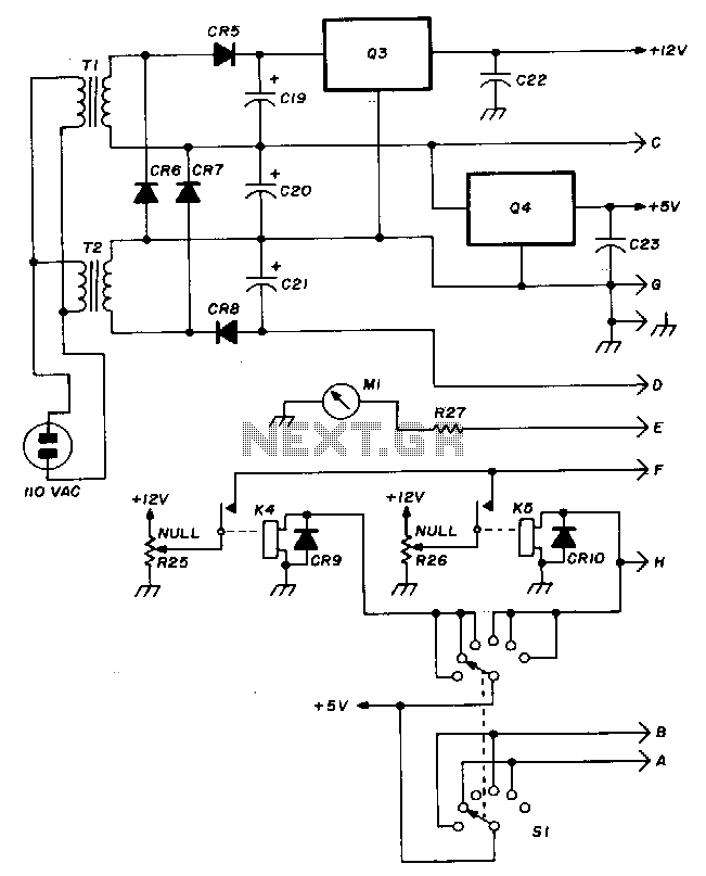
The Hewlett-Packard HSCH-3486 zero-bias Schottky diode is utilized as the detector. To avoid employing a modulation detection method, a chopper-stabilized operational amplifier is implemented. The chopper operational amplifier effectively converts the input DC voltage to AC, amplifies it, and...
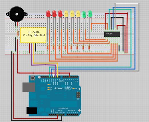
This is a tutorial for beginners who have recently started learning about electronics. The author has prior experience in programming with C and Python. The schematic presented in this tutorial is designed for novice electronics enthusiasts who are transitioning from...
A simple rotating display. Just spin and enjoy. While the "Air display" is rotating, it writes the message on the air. Because of the "persistence of vision", you will be able to read the message. The operation is super...

The 1-Wire Net, or MicroLAN (by Maxim-Dallas), is a straightforward method for connecting slow devices such as sensors, relay drivers, and switches using basic components. These components include a 1-Wire protocol handler, an interface to the external world, and...
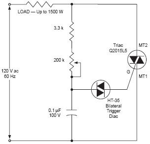
The DIAC, or diode for alternating current, is a trigger diode that conducts current only after its breakdown voltage has been momentarily exceeded. Most DIACs are utilized in applications requiring a switching function in AC circuits. The DIAC is a...