
Numeric water level indicator- liquid level sensor circuit diagram with 7 segment display

The circuit operates by monitoring the levels of a reservoir and encoding the sensed values into a binary format suitable for display. The 74148 IC encodes up to eight input lines into three output lines, allowing for efficient data representation. The outputs of the 74148 are then connected to either a HEX display or a 7447 decoder driver, depending on availability and project requirements.
In the case of using the HEX display, the 4-bit binary input, which is derived from the sensed levels, directly corresponds to a hexadecimal digit, simplifying the process of visual representation. The HEX display eliminates the need for additional decoding, allowing for a straightforward connection to the encoder outputs.
If opting for the 7447 decoder driver with a standard 7-segment display, the circuit retains its functionality, although it requires the additional step of decoding the binary output. The 7447 converts the binary input into a format that can drive the 7-segment display, illuminating the appropriate segments to represent the encoded value visually. The design acknowledges that the fourth input of the 7447 is not required for this application, as the maximum encoded value is seven (binary 111).
This circuit design is advantageous for projects requiring level monitoring and display, providing a clear and efficient means to visualize data. It is adaptable to component availability while maintaining functionality and clarity in the representation of reservoir levels. Proper attention to the connections and power supply for the ICs and display components is essential to ensure reliable operation.Here we define 7 levels in thereservoir. The sensed values are connected to an encoder circuit. The encoder circuit consist of a 74148 IC, which is a 8 line to 3 line encoder. Next section is the HEX Display` which is a special type of 7 segment display. It is easier to use than the regular seven-segment display because it is already decoded. Each hexadecimal digit is displayed when its 4 bit binary equivalent is received as input, as shown in the truth table below. If it is difficulty to get a HEX Display` you can use ordinary 7 segment display with decoder driver IC 7447.
Hence the encoded values are displayed. This circuit will be really helpful for your project. You can neglect the 4th input (D) of 7447 because we are using this circuit to code up to 7 level, that is upto binary 111. Hence there is no need of the 4th input of 7447. 🔗 External reference
Related Circuits
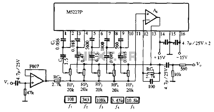
The M5227P is an application circuit designed for a graphic equalizer. Its control curve operates on a logarithmic frequency axis to represent the rate, requiring the same control curve pitch to ensure that all bands achieve maximum lift or...
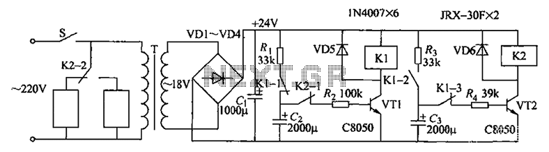
Artificial hatching or breeding of tropical fish requires the configuration of an oxygen pump and a circulating pump for the fish pond. Continuous operation of both pumps not only wastes energy but also risks damaging components. This example illustrates...
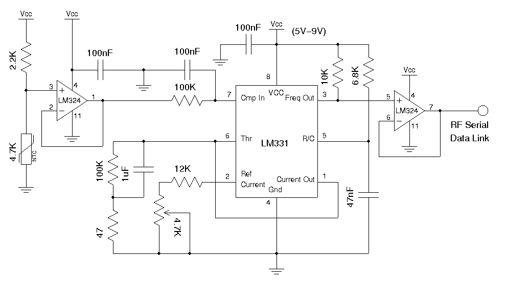
A wireless temperature sensor allows temperature measurements to be taken anywhere within the range of the transmitter and receiver. One straightforward approach to achieve this is by utilizing a voltage-to-frequency conversion chip in conjunction with an analog temperature sensor,...
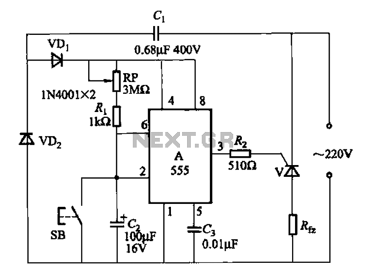
The 555 integrated circuit (IC) is utilized in a delay circuit configuration. It transitions from a high to a low output state when a button (SB) is pressed. The output remains high for a specified delay period before transitioning...
This is a simple flashing LED circuit featuring two LEDs and two NPN transistors. It demonstrates the behavior of transistors and capacitors, and it can be used in an oscillating configuration. The circuit consists of two NPN transistors, which function...
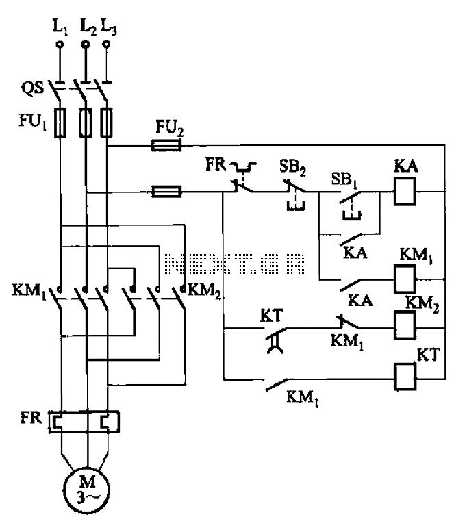
The circuit illustrated in Figure 3-127 utilizes a time relay (KT) in place of a speed relay. The timing duration is adjustable and typically set between 1 to 2 seconds. This circuit is designed to operate effectively in dusty...